F5HM Circuit Diagrams.pdf - 第82页
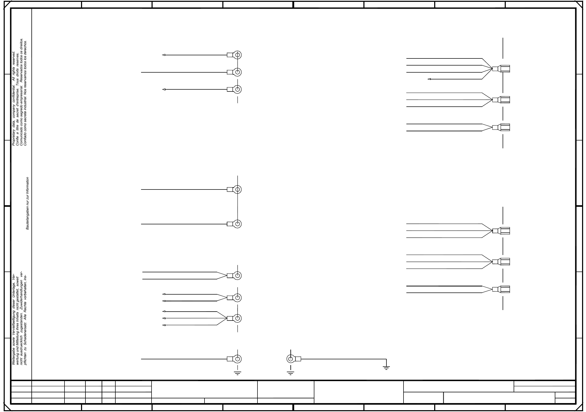
2 Circuit Diagr ams 82 0034582 2-010201TD3 F5 HM servo unit, base (c onnector p in assignme nt) (Sh. 1 of 3) + Bl. SIEME NS AG Zustand A enderung Datum Name Ers. d. Ers. f . Ur spr. Blatt Bearb. Norm Gepr. Datum = F5-HM …
2 Circuit Diagrams 81
00345822-010101LD3 Circuit diagram, power supply (Sh. 4 of 4)
pkgr / 0,25mm²
pkgr / 0,25mm²
pkgr / 0,25mm²
pkgr / 0,25mm²
Pin 20
Pin 24
pk / 1,5mm²
Pin 18
-15V
A
B
C
D
+15V
X4vk:2
X4vg:2
From plug
Backplane, X-axis I A13
Backplane, DP1-axis IC A18
Anti-crash card, A10
To plug
Backplane, DP1-axis I A15
Backplane, Z-axis I A16
Backplane, star I A17
Backplane, Z-axis IC A19
X2:4
X7vb:3
Cable 00321582-02 (incl. in cable set)
Ballast circuit, A16
vi / 1,0mm²
X13:c2
To plug
Meas. socket, MB8
X4vf:2
X4vd:2
X4vc:2
Backplane, Y-axis I A14
X6vb:2
X6va:2
Pin 4
X14:7
X14:3
X4vd:1
pk / 0,25mm²
vi / 1,5mm²
C
B
A
3
vi / 1,5mm²
vi / 1,5mm²
vi / 1,5mm²
vi / 1,5mm²
vi / 1,5mm²
4321
SMD Placement System
4
4
Power supply unit
From plug
1L+/5L+
2L+
X2:1
X2:2
X2:3
X2:5
From plug
From plug
Meas. socket, MB9
Backplane, X-axis I A13
Pin 10
vi / 0,25mm²
X4vf:1
Pin 6
X4vg:1
X4vk:1
X6va:1
21
8765
+
Sh.
SIEMENS AG
Zustand Aenderung Datum Name Ers. d.Ers. f.Urspr.
Sheet
Bearb.
Norm
Gepr.
Datum
=
Power supply
Document st.
10.02.99
10.02.99
10.02.99
10.02.99
Tuth
#
Circuit diagram
00345822-010101LD3
PL EA1 E
besondere fuer den Fall der Patenterteilung oder GM-Eintragung.
pkgr / 0,25mm²
pkgr / 0,25mm²
Star point 008
Star point 009
pk / 1,0mm²
SIPLACE 80F5-HM
Deu
Deu
Deu
01
01
01
Function status
Product status
Backplane, Y-axis I A14
Anti-crash card, A10
X4vc:1
X11g:5
Backplane, Z-axis IC A19
Backplane, DP1-axis IC A18
Backplane, DP1-axis I A15
Backplane, Z-axis I A16
Backplane, star I A17
X11g:1
X2:6
X6vb:1
X7va:3
pkbk / 0,25mm²
pkbk / 0,25mm²
pkbk / 0,25mm²
pkgr / 0,25mm²
pkbk / 0,25mm²
pkgr / 0,25mm²
Front plate
E
F F
E
D
Backplane, X-axis I A13
Backplane, Y-axis I A14
87654
Power supply unit
pkbk / 0,25mm²
pkbk / 0,25mm²
pkbk / 0,25mm²
pkbk / 0,25mm²
From plug
From plug
vio / 1,5mm²
pkbk / 0,25mm²
2 Circuit Diagrams 82
00345822-010201TD3 F5 HM servo unit, base (connector pin assignment) (Sh. 1 of 3)
+
Bl.
SIEMENS AG
Zustand Aenderung Datum Name Ers. d.Ers. f.Urspr.
Blatt
Bearb.
Norm
Gepr.
Datum
=
F5-HM servo unit, base
1
87321
n.c.
Deu
Ha
Deu
01
02
01
Function status
Product status
Document status
10.02.99
7
Axis, Enable
Tacho-
n.c.
Axis, Enable (+15V)
n.c.
1L+
Note!
have to be cut out.
1
SIPLACE 80F5-HM
A
D
C
543
n.c.
n.c.
Distance sensor
Anti-crash prox.sw. 2 Y-axis
E
F F
E
Tacho-
Axis, Enable
B
A
2
n.c.
+5V1
Axis, Enable (+15V)
Anti-crash cardPin
23
+24V+15V
SMD Placement System
3
Distance sensor
n.c.
n.c.
Distance sensor
B
C
D
6
*
*
ba
Anti-crash prox.sw. 1 Y-axis
Anti-crash prox.sw. 2 X-axis
Anti-crash prox.sw. 1 X-axis
n.c.
2
4
n.c.
Tacho-
8
n.c.
n.c.
"Crash" signal to S5 ->
Tacho-
Axis, Enable
1L+
65
2
T
T
Anti-crash prox.sw. 2 X-axis
Anti-crash prox.sw. 1 X-axis
Anti-crash prox.sw. 2 Y-axis
Anti-crash prox.sw. 1 Y-axis
1
5
5
1
8
2L+ 7
1
T
26
3
9
Axis, Enable
19
22
6L+
7L+
1L+
6
1L+
2L+
4
All pins marked with a cross,
63
Socket contacts 0.5-2.1mm²
Tacho+
n.c.
n.c.
4
5
41
6
Axis, Enable (+15V)
n.c.
Tacho+
n.c.
1
key
n.c.
Tacho+
n.c.
20
5
key
Pin 1-3 pin contacts 0.5-2.1mm²
n.c.
1
e
10
X2
1
63
2
X3
X4
X14
X2
13
*
X3
7L+
+12V
1L-
14
5
6
key
15
16
17
25
3
6
18
*
key
7
4
1L-
Socket contacts 0.5-2.1mm²
Pin contacts 0.5-2.1mm²
Pin 4-6 socket contacts 0.5-2.1mm²
Contact designation
9
10
11
12
3
2
5
4
2L+/5L+
6L+
2
a
Axis, Enable (+15V)
Tacho+
6
b
2
key
21
1L-
key
7L+
"Crash" signal to S5 ->
Distance sensor
n.c.
+24V
X4
JP 1
2
X14
9
T
T
+15V +24V
5
2
29
30+5V
1L-
31
6L+
2
-15V
+5V
key
g
27
28
24
1L+
1
6
*
32
8
10.02.99
Tuth
#
(connector pin assignment)
00345822-010201TD3
07.07.99
10.02.99
PL EA1 E
2 Circuit Diagrams 83
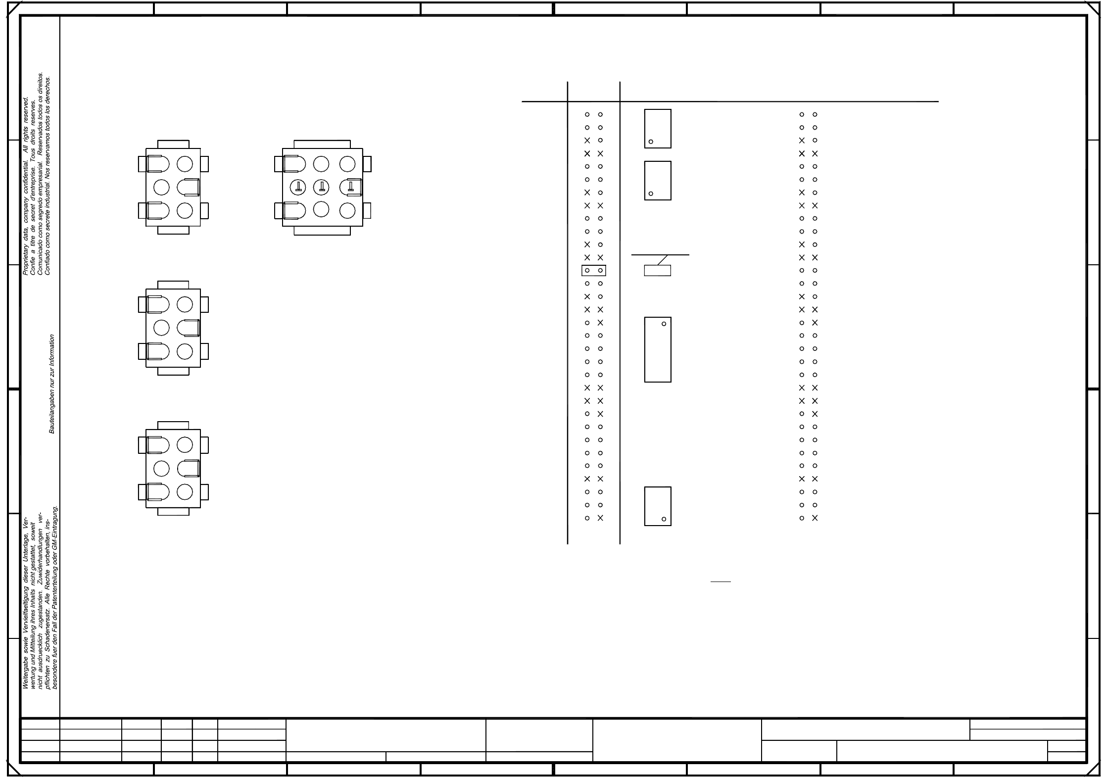
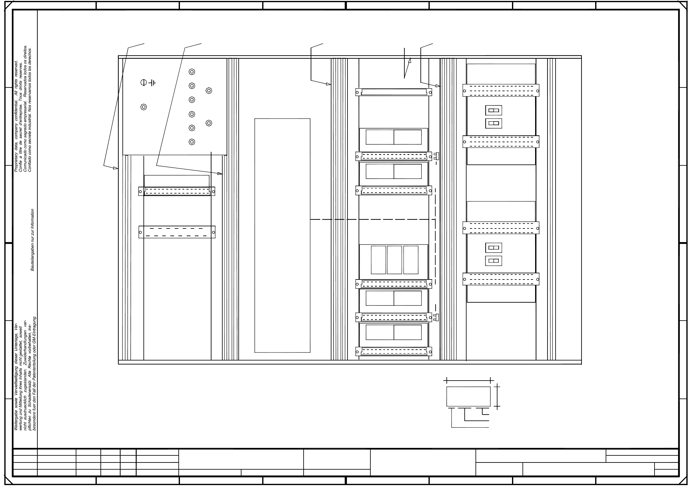
00345822-010201TD3 F5 HM servo unit, base (viewed from the front) (Sh. 2 of 3)
18
16
14
12
10
8
14
12
32
X12
8
GND
A: Identification label, assembly inscription acc. to VA-F-510-001
A
43
Z-axis, IC-head "A19"
X4
X3
4
009
Anti-crash card X11
Apply the following labels on the inside
65
765
* Note
8
26
1
2
S2
1
2
12V
Prepare and apply
8
16
E
D
C
4
6
6L+
DP1-axis, IC-head "A18"
005
22
Inscription
* Note
SIPLACE 80F5-HM
18
40
Manufacturer/location acc. to SN 37040
Date (year/month/day) acc. to SN 01007
Series number
20
18
16
D
C
S1
2
1
004
2
Fan unit A20
Note !
tape A
12
10
001
6
4
2
A13
Servo amplifier X-axis
10
321
Dynamic brake X-axis
S1 = 1Gantry 1:
006
7L+
B: Inspection label Identification: testing engineer, month, year
5V
7
003
F
002
2L+
007
20
18
008
Star I "A17"
Z-axis I "A16"
DP1-axis I "A15"
Part 005
of the Z servo amplifiers for the SP and the IC head.
Install the contact springs only on the front side and only in the lower guide rails
F
B
2
according to drawing no.
tape D
2
S2 = 2
Inscription
26
28
30
8
1
SMD Placement System
3
Part 006
Insert contact springs for the guide rails parts 005 and 006.
10.02.99
Tuth
#
(viewed from the front) 00345822-010201TD3
07.07.99
10.02.99
PL EA1 E
20
18
16
14
12
10
8
Deu
Ha
Deu
01
02
01
Function status
Product status
Document status
10.02.99
24V
1L+
tape B
(flush with the front plate):
Ballast X13
30
32
28
14
22
24
inscription tapes
6
4
2
A14
Servo amplifier Y-axis
Dynamic brake Y-axis
1
2
S2 S1
X3
X4
32
30
28
26
24
22
Switch settings:
Power supply unit
B
24
E
A
2L+/5L+
Inscription
tape C
Inscription
00345822-xx
AA - BBBB - CCCC
SIEMENS PLEA1
6
4
2
32
30
28
26
24
22
20
+
Sh.
SIEMENS AG
Zustand Aenderung Datum Name Ers. d.Ers. f.Urspr.
Sheet
Bearb.
Norm
Gepr.
Datum
=
F5-HM servo unit, base
00345821-010101NDI