F5HM Circuit Diagrams.pdf - 第85页
2 Circuit Diagr ams 85 0033706 5-020102 LD3 X-moto r , S23 for length of the lin es and location of the in scripti on labels . Refe r to dr awing 00 337065 -010102V D3 1 1 SMD-Placement System Siplace S23 Product st atus…
2 Circuit Diagrams 84
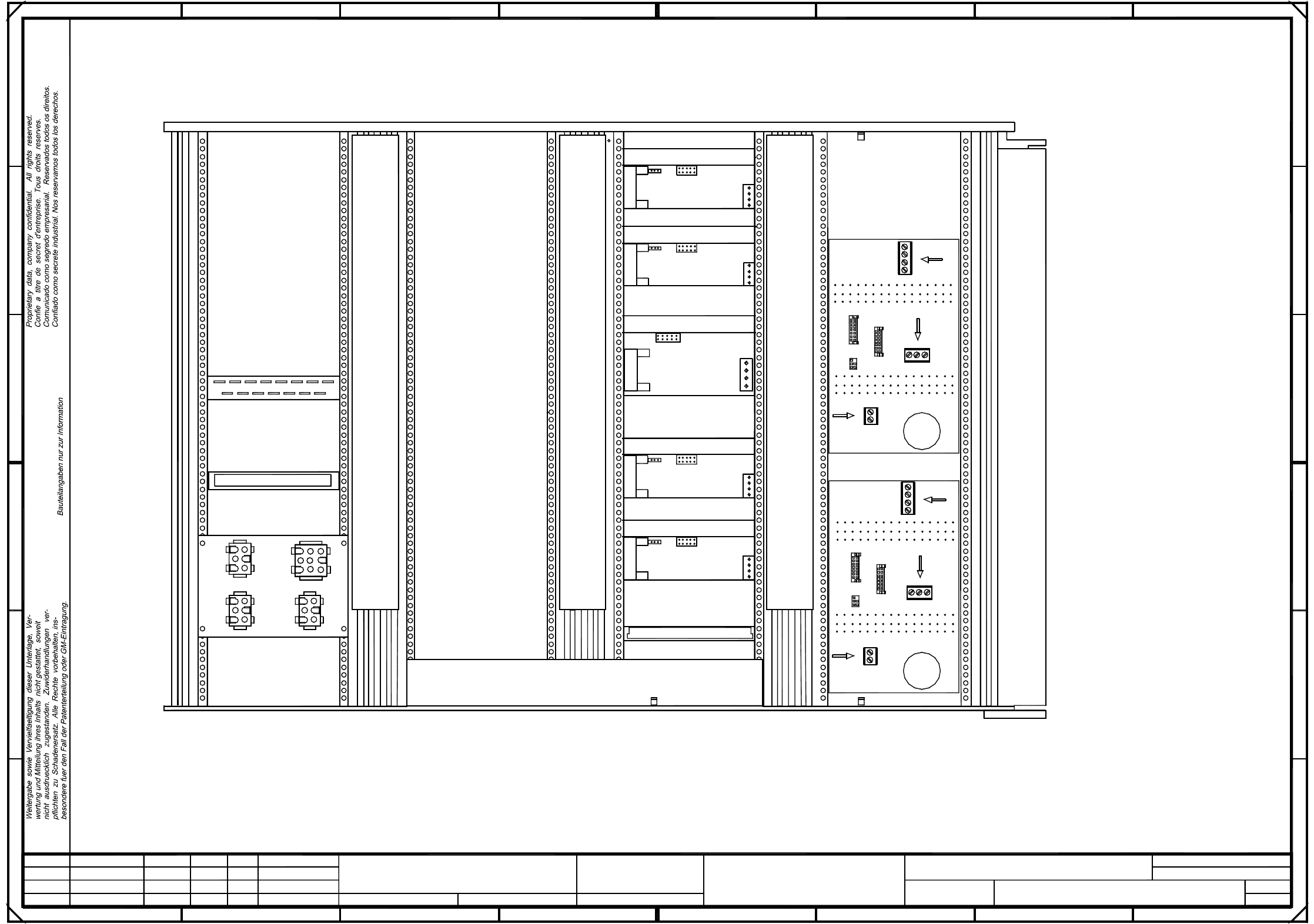
00345822-010201TD3 F5 HM servo unit, base (viewed from the back) (Sh. 3 of 3)
12
10
8
6
4
14
16
00345822-010201TD3
(Rueckansicht)
#
Tuth
10.02.99
10.02.99
07.07.99
10.02.99
Document status
Product status
Function status
01
02
01
Deu
Ha
Deu
18
20
6
C1
22
C1
X13
26
32
30
SMD Placement System
3
3
12
18
6
Anti-crash card X11
10
10
8
30
28
26
8
Cable duct 004
X2
30x30 l=250mm
14
21
29
Ballast
X2
X4
X6
8
6
4
C
D
X1 (vg)
2
A16
Z-axis I
X3
X2
X4
28
1
+
Sh.
SIEMENS AG
Zustand Aenderung Datum Name Ers. d.Ers. f.Urspr.
Sheet
Bearb.
Norm
Gepr.
Datum
=
F5-HM servo unit, base
2
X1 (vk)
23
Cable duct 001
41
7
60x30 l=300mm
X2
49
X3
X1 (vc)
5
2
1
1
4
23
1
5
32
X6
1
23
71
X1 (vf)
A15
DP1-axis I
X3
X4
X8
X1
X8
X4
1
60x30 l=300mm
3
12
X4
60
Y-axis "A14"
X-axis "A13"
SIPLACE 80F5-HM
40
B
22
X1 (vd)
2311
X4
A17
X2
10
16
14
12
2
32
Fan unit A20
Star I
22
24
34
30
32
Cable duct 002
DP1-axis , IC-head
X3
21
A
1
8
X3 X2
1
4
1
67
30
28
26
24
X7
123
4
12
10
2
28
2
18
4
20
A19
16
14
20
18
16
D
C
B
A
8
4
2
2
Z-axis , IC-head
X3
60x30 l=300mm
X12
X2
3
X7
1
X3
1
22
34
X3
X14
24
E
F F
E
20
52
1
Cable duct 003
X1
X2
Power supply
A18
26
24
6
PL EA1 E
2 Circuit Diagrams 85
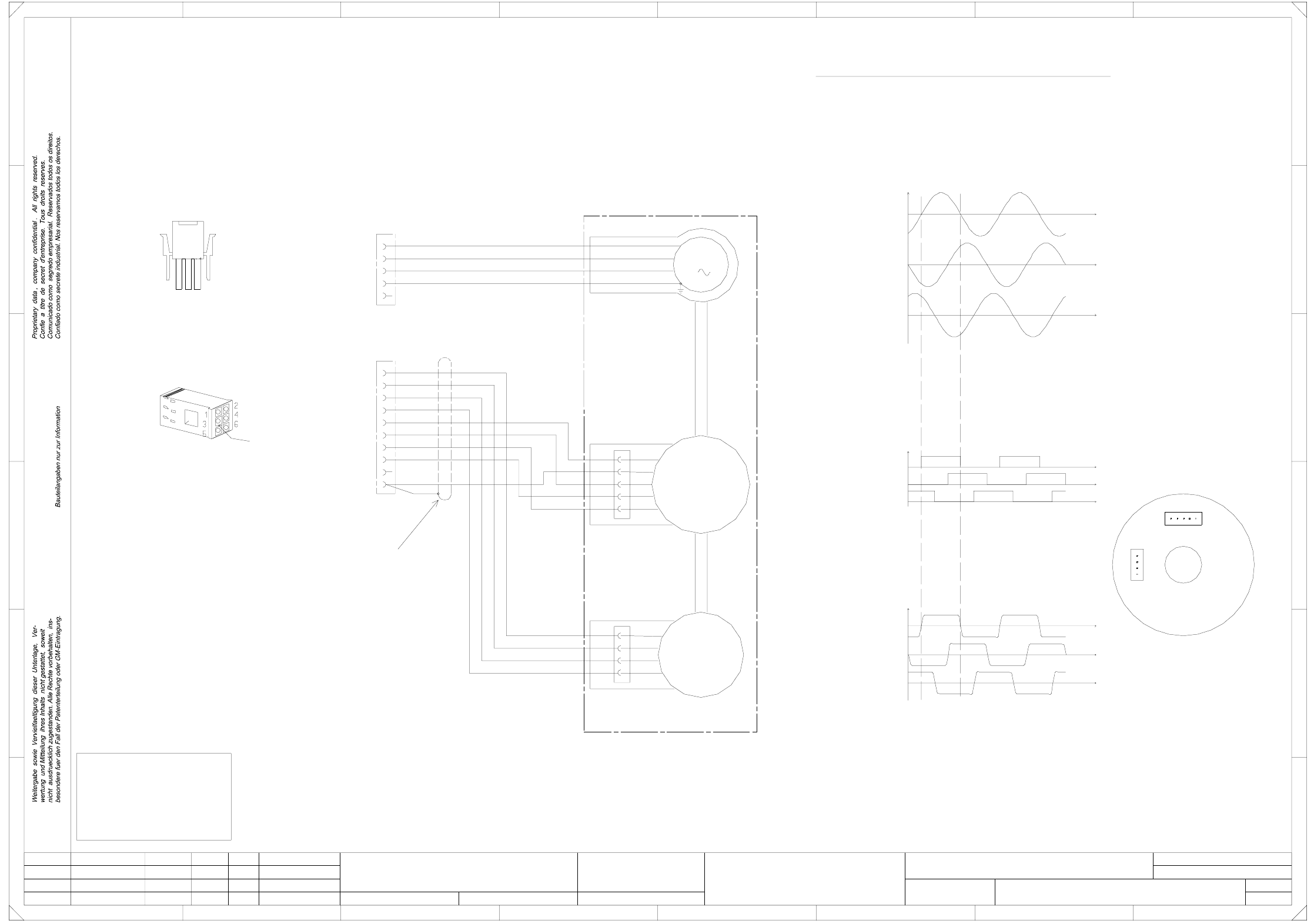
00337065-020102LD3 X-motor, S23
for length of the lines and location of the inscription labels.
Refer to drawing 00337065-010102VD3
1
1
SMD-Placement System Siplace S23
Product status
Doc. status
Function status
=
Datum
Gepr.
Norm
Bearb.
Blatt
Urspr. Ers. f. Ers. d.NameDatumAenderungZustand
SIEMENS AG
Bl.
+
FOR INFORMATION ONLY !
This document will not
be replaced,
if changes are made!
1
1
Mot. W
Mot. PE
E
F
4
vi
RSE U
RSE V
RSE W
RSE (+5V)
RSE (GND)
9
5
X3**
3
Tacho W (X13.3)
Tacho U (X13.1)
F
E
23
B
C
D
Mot. U
Mot. V
00337065-02 (W1)
All signals are shown by clockwise rotation (looking at the driving shaft)!
Tacho TP
Tacho W
2
ye
4 ye/gn
4
wh
ye
gn
br
Tacho
1
Tacho against TP (X13.4)
3
EMK motor
3
C
D
Instructions on the inscription and appearance of the labels
are given in the labeling guidelines for cable sets
specified in the parts list.
1FT3035-6AZ99-9
MATE-N-LOCK
plug casing
3
Connect screen to Pin 10
8
6 wh/br
1
8
bk
2rd
3
RSE U (X13.5)
RSE V (X13.6)
RSE W (X13.7)
Key
10
rd
XR
1
21
1
A
567
M
rd
ye
RSE against RSE (GND) (X13.10)
00337065-02 (W2)
XR
XT
RSE
Tacho
45
8
V (X3.2) to W (X3.3)
Ground at V
test probe at U
U (X3.1) to V (X3.2)
W (X3.3) to U (X3.1)
Calibration of the Tacho/RSE unit for the stator winding
ye/gn
bk
Tacho V (X13.2)
wh
2ye
3gn
4br
5
X13**
67
2
A
B
7 wh/bk
Tacho V
1
Tacho U
or
4
or
vi
wh/br
rd
5
wh/bk
RSE
XT
X motor, S23
#
Werner
21.08.98
12.11.98
18.08.98
18.08.98
02
01
02
Wer
Deu
Deu
PL EA1 E
of the plug, as shown on the label.
The sequence of
numbers is as viewed from the reverse
Cable
00337065-020102LD3
2 Circuit Diagrams 86
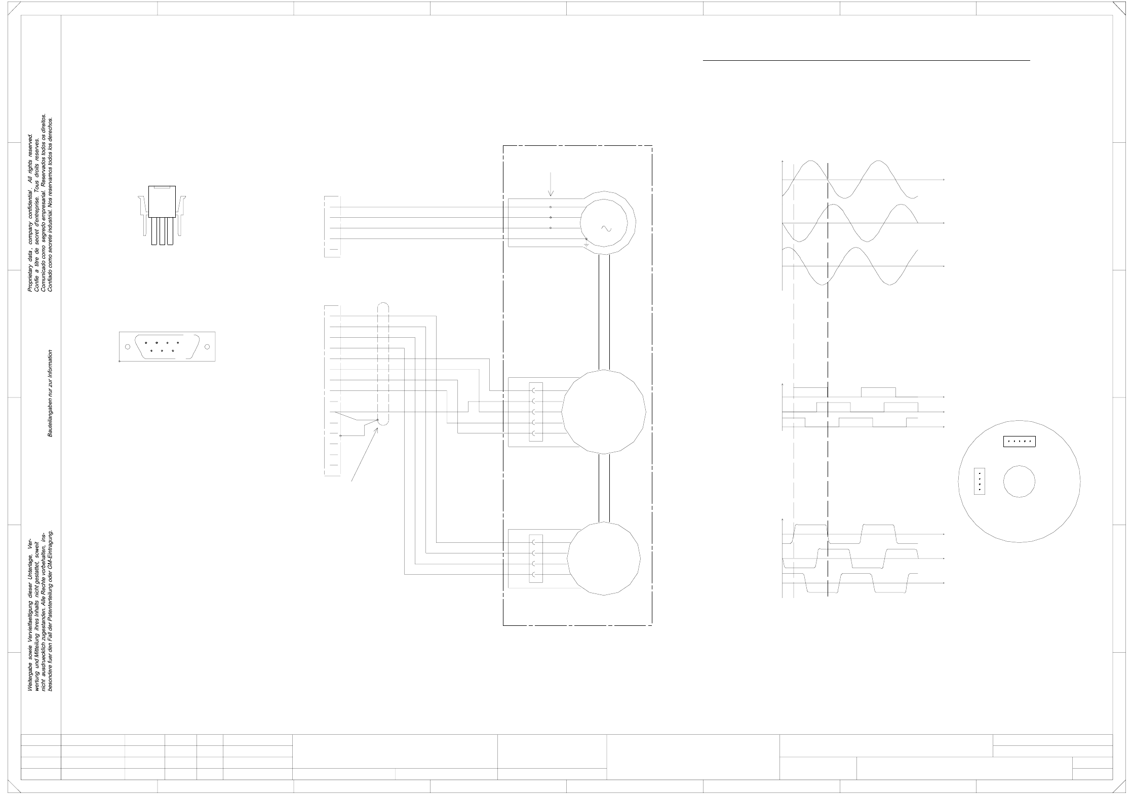
00337066-020102LD3 Y-motor, S23
1
1
SMD-Placement System Siplace S23
Product status
Doc. status
Function status
Refer to drawing 00337066-010102VD3
for length of the lines and location of the inscription labels.
specified in the parts list.
are given in the labeling guidelines for cable sets
Instructions on the inscription and appearance of the labels
Tacho V (X32.9)
Tacho W (X32.2)
or
M
3
1
1
XR
XT
RSE
Tacho
Mot. U
Mot. V
00337066-02 (W1)
00337066-02 (W2)
RSE against RSE (GND) (X32.13)
All signals are shown for clockwise rotation (looking at the driving shaft)!
Connect screen to pin 13,
Key
13
10 br
3
MATE-N-LOK
plug casing
1
4 wh/bk
12 rd
5
234
109
...
C
D
F
E
23
B
3 8
54
vi
wh/br
rd
8
fold back the screen braid
and connect to the plug casing
XT
XR
ye/gn
bk
rd
5 761
1
2
C
D
E
F
4
678
A
B
1FT3046-6AZ99-9
6
14
7
2
3
Crimp connections
SUB-D plug
1
18.08.98
18.08.98
02
01
02
Wer
Deu
Deu
15
via the cable grip.
A
PL EA1 E
00337066-020102LD3
Y motor, S23
#
Werner
21.08.98
12.11.98
=
Datum
Gepr.
Norm
Bearb.
Blatt
Urspr. Ers. f. Ers. d.NameDatumAenderungZustand
SIEMENS AG
Bl.
+
Tacho U (X32.1)
Mot. W
Mot. PE
1
22
33
4ye/gn
5
Tacho U
1
Tacho V
Tacho W
Tacho TP
wh
9ye
2gn
X31*
1
V (X31.2) to W (X31.3)
X32*
11 wh/br
Ground at V
EMK Motor
Calibration of the tacho/RSE unit for the stator winding
RSE U (X32.3)
or
vi
RSE U
RSE V
RSE W
RSE (+5V)
RSE (GND)
1
2
3
4
wh
ye
gn
br
Tacho
1
2
3
4
or
Test probe at U
U (X31.1) to V (X31.2)
W (X31.3) to U (X31.1)
5wh/bk
RSE
RSE V (X32.11)
RSE W (X32.4)
Tacho against TP (X32.10)