F5HM Circuit Diagrams.pdf - 第86页
2 Circuit Diagr ams 86 0033706 6-020102 LD3 Y -mo tor , S23 1 1 SMD-Placement System Siplace S23 Produ ct status Doc. sta tus Function status Refe r to dr awing 0 0337 066-010 102VD3 for l engt h of the l ines a nd loca …
2 Circuit Diagrams 85
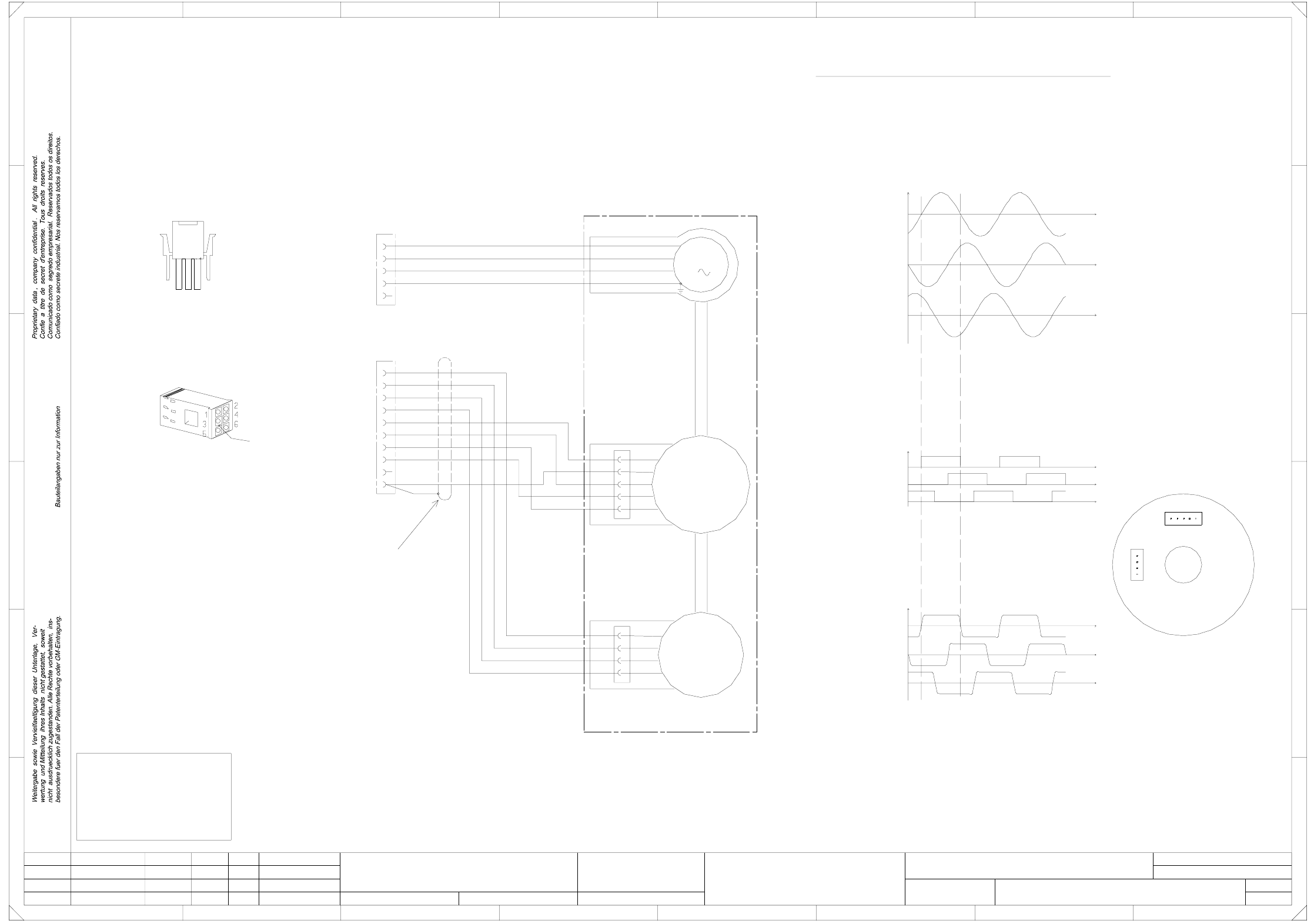
00337065-020102LD3 X-motor, S23
for length of the lines and location of the inscription labels.
Refer to drawing 00337065-010102VD3
1
1
SMD-Placement System Siplace S23
Product status
Doc. status
Function status
=
Datum
Gepr.
Norm
Bearb.
Blatt
Urspr. Ers. f. Ers. d.NameDatumAenderungZustand
SIEMENS AG
Bl.
+
FOR INFORMATION ONLY !
This document will not
be replaced,
if changes are made!
1
1
Mot. W
Mot. PE
E
F
4
vi
RSE U
RSE V
RSE W
RSE (+5V)
RSE (GND)
9
5
X3**
3
Tacho W (X13.3)
Tacho U (X13.1)
F
E
23
B
C
D
Mot. U
Mot. V
00337065-02 (W1)
All signals are shown by clockwise rotation (looking at the driving shaft)!
Tacho TP
Tacho W
2
ye
4 ye/gn
4
wh
ye
gn
br
Tacho
1
Tacho against TP (X13.4)
3
EMK motor
3
C
D
Instructions on the inscription and appearance of the labels
are given in the labeling guidelines for cable sets
specified in the parts list.
1FT3035-6AZ99-9
MATE-N-LOCK
plug casing
3
Connect screen to Pin 10
8
6 wh/br
1
8
bk
2rd
3
RSE U (X13.5)
RSE V (X13.6)
RSE W (X13.7)
Key
10
rd
XR
1
21
1
A
567
M
rd
ye
RSE against RSE (GND) (X13.10)
00337065-02 (W2)
XR
XT
RSE
Tacho
45
8
V (X3.2) to W (X3.3)
Ground at V
test probe at U
U (X3.1) to V (X3.2)
W (X3.3) to U (X3.1)
Calibration of the Tacho/RSE unit for the stator winding
ye/gn
bk
Tacho V (X13.2)
wh
2ye
3gn
4br
5
X13**
67
2
A
B
7 wh/bk
Tacho V
1
Tacho U
or
4
or
vi
wh/br
rd
5
wh/bk
RSE
XT
X motor, S23
#
Werner
21.08.98
12.11.98
18.08.98
18.08.98
02
01
02
Wer
Deu
Deu
PL EA1 E
of the plug, as shown on the label.
The sequence of
numbers is as viewed from the reverse
Cable
00337065-020102LD3
2 Circuit Diagrams 86
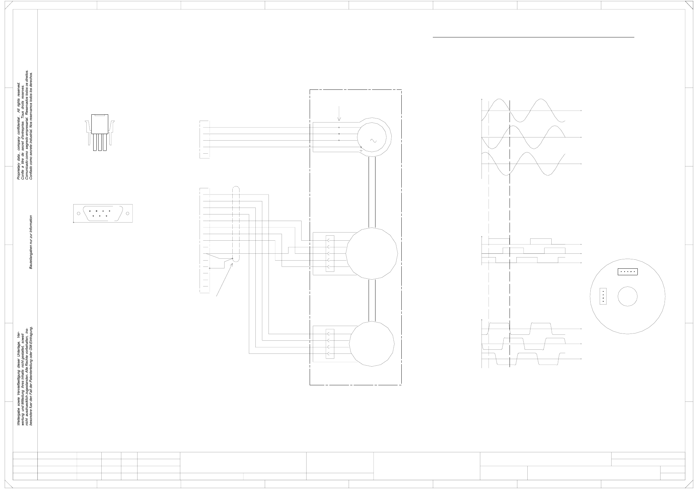
00337066-020102LD3 Y-motor, S23
1
1
SMD-Placement System Siplace S23
Product status
Doc. status
Function status
Refer to drawing 00337066-010102VD3
for length of the lines and location of the inscription labels.
specified in the parts list.
are given in the labeling guidelines for cable sets
Instructions on the inscription and appearance of the labels
Tacho V (X32.9)
Tacho W (X32.2)
or
M
3
1
1
XR
XT
RSE
Tacho
Mot. U
Mot. V
00337066-02 (W1)
00337066-02 (W2)
RSE against RSE (GND) (X32.13)
All signals are shown for clockwise rotation (looking at the driving shaft)!
Connect screen to pin 13,
Key
13
10 br
3
MATE-N-LOK
plug casing
1
4 wh/bk
12 rd
5
234
109
...
C
D
F
E
23
B
3 8
54
vi
wh/br
rd
8
fold back the screen braid
and connect to the plug casing
XT
XR
ye/gn
bk
rd
5 761
1
2
C
D
E
F
4
678
A
B
1FT3046-6AZ99-9
6
14
7
2
3
Crimp connections
SUB-D plug
1
18.08.98
18.08.98
02
01
02
Wer
Deu
Deu
15
via the cable grip.
A
PL EA1 E
00337066-020102LD3
Y motor, S23
#
Werner
21.08.98
12.11.98
=
Datum
Gepr.
Norm
Bearb.
Blatt
Urspr. Ers. f. Ers. d.NameDatumAenderungZustand
SIEMENS AG
Bl.
+
Tacho U (X32.1)
Mot. W
Mot. PE
1
22
33
4ye/gn
5
Tacho U
1
Tacho V
Tacho W
Tacho TP
wh
9ye
2gn
X31*
1
V (X31.2) to W (X31.3)
X32*
11 wh/br
Ground at V
EMK Motor
Calibration of the tacho/RSE unit for the stator winding
RSE U (X32.3)
or
vi
RSE U
RSE V
RSE W
RSE (+5V)
RSE (GND)
1
2
3
4
wh
ye
gn
br
Tacho
1
2
3
4
or
Test probe at U
U (X31.1) to V (X31.2)
W (X31.3) to U (X31.1)
5wh/bk
RSE
RSE V (X32.11)
RSE W (X32.4)
Tacho against TP (X32.10)
2 Circuit Diagrams 87
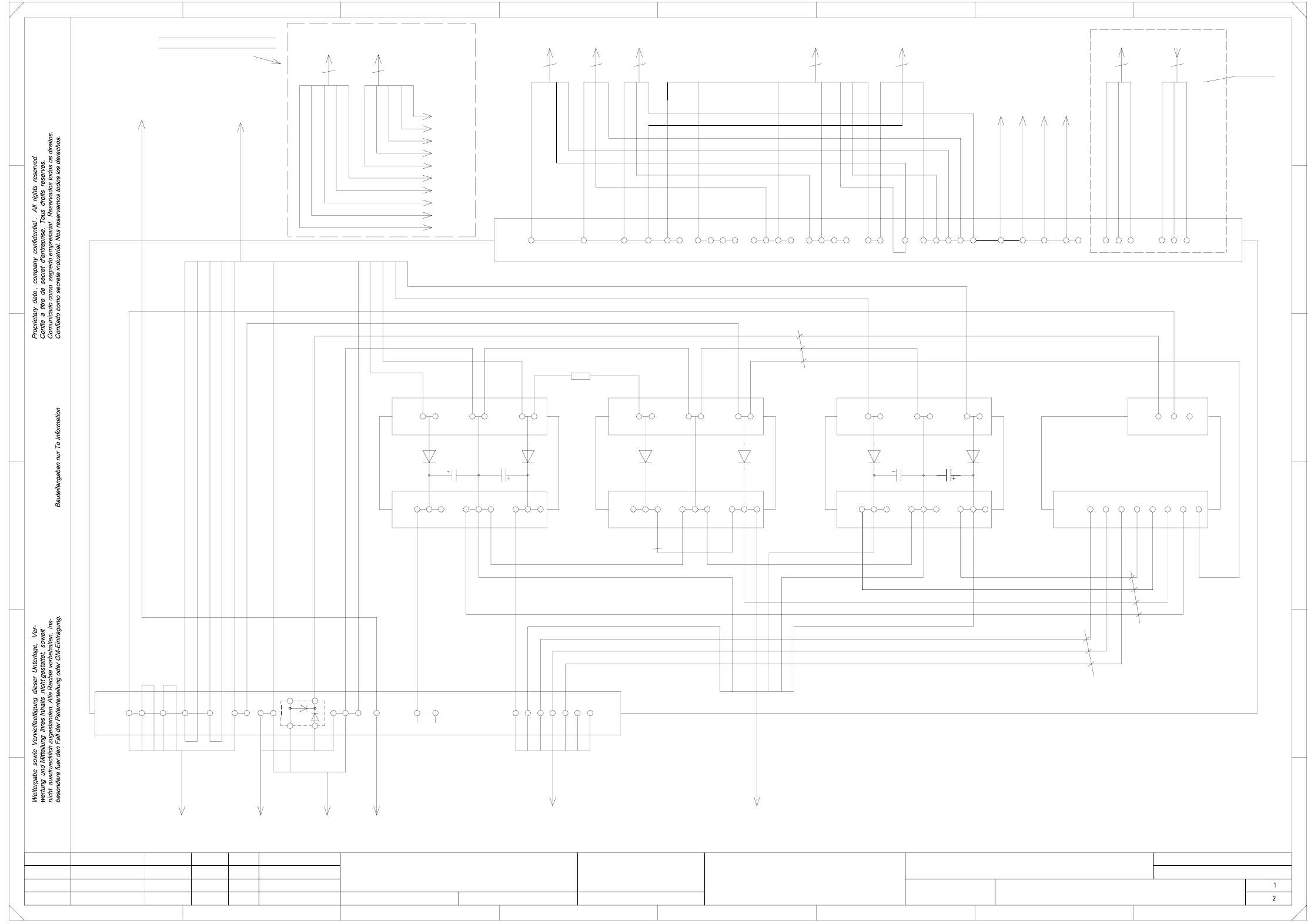
00337342-030101LD3 Circuit diagram, terminal panel, righthand side (Sh. 1 of 2)
WPC interface:
applies to SIPLACE 80Fxx only
xxx-xx
lefthand side
WPC interface
To
br
00344539
gn/ye
bl
br
PE
-xx
Option:
When a UPS
is used
make the
terminal
Leh
Leh
Leh
03
01
01
21.10.98
12.03.98
08.06.98
21.10.98
Tuth
#
Circuit diagram, terminal panel
00337342-030101LD3
4,7 Ohm / 5W
R1
21
PL EA1 E5
SMD-Placement System Siplace S23
Product status
Doc. status
Function status
righthand side
L1
27
(K2)
1,5mm²
3
4
6
2,5mm²
5
2L-
wh
wh
321
X1
65
power supply
gn/ye
gn/ye
2L- 8
To
(K1)
YS10-W1
To
To
bk
6
6
gn/ye
C511-W1
54
A5
784
1mm² bk
br
gr
Spare
1
servo
1
PE PE PE
78
Spare
pk
1
2
1
A3
4
54327
C
5
C510-W1
B
D
C
A
10mm²
4
1L+ 2
F
E
81818
4
1L+ 1
1L+ 4
1L+ 11
6
To
23
servo unit
5
711543
X2
1
A4
5
A2
56
123
*904/X211,X212
3
76
tape cutter 1
Y636-
Y636-
PE
19
23
3
L3
1L+
L1L1L1
8 26
5
4
bk10mm²
L3
2L+ 3
F
21
br
gn
bl/bk
17
3
X207
X206
C5 09-W1
*935/X2
6L2
4
8
1L+
6mm²
78921
6
X2
2
X1
X1
54
8
N PE
11
bk
bl
br
PE PE PE
5
C0530
2L+
L3
To cable
6L+ 9
7L+ 10
5L+
3
1L-
1mm²
To
1mm²
32
L2
6
D
E
N
C0530
To
7
1mm²
bl/bk
br
gn
gn
(re)
1
bk
gn/ye
L2
1L+
wh
5
bl
br
gr
gn
2
br
wh
br
1
11
1
10
5
9
tape cutter 2
3
2L-
gn
ws
ge
bl
bl/bk
C938
C935
PE
C708
C709
1L+
6mm²
X31
bl/bk
C560
To cable
1
bk
gn
1L-
1mm²
*952
2L-
6
19
12V
10
N
1
00300161-06 C523-W1
4L+
(K1)3L+ 5
wh
power supply
unit
1
wh
N
bl
bk
gn/ye
wh
2L-
gr
sw
gr
1mm²
6L+ 9
rd
2L+
br
br
To
bl
star point 007
To
bl
bk
gn/ye
servo unit
bk
gr
To
interface,right
C956
To control unit
wh
C955
To
*938/X16
control unit
bk
bl/bk
gn1mm²
2L+/5L+
+7L switched
gr
6L+ unswitched
To
power supply
4
C506-W1
2
5
rectifier VI-
rs
C517C51600344212-xx
4
wh
wh
6
+7L switched
gn/ye
1mm²
6
wh
2L+/5L+
8
ye
6L+ unswitched
righthand side, xxx
00344540
gn/ye
bl
br
br
bk
bl
bl
N5PEN4
-xx
1,5mm²
br
(+24V)
(K2)
To
To servo unit
connections
and remove
the
jumper
X206:4-5
To UPS From UPS
pk
br
gn/ye
bk
bl
br
gn/ye
wh
bk
bk
Dxxx
WPC interface
To
xxx-xx
bk
br
3
gr
ye
0,5mm²
bl/bk
gn/ye
bk
bl
bk
X206:PE
X206:N
X206:L3
X206:L2
X206:L1
X206:PE
X206:N
X206:L3
X206:L2
X206:L1
=
Datum
Gepr.
Norm
Bearb.
Blatt
Urspr. Ers. f. Ers. d.NameDatumAenderungZustand
SIEMENS AG
Bl.
+
(rc)
X2
9
X1
6
gn/ye
gn/ye
2
rd
*935/X3
10
N
3
L3 PE
interface,left
2
1
wh
7L+ 10
7
2L+
2L-
2L+/5L+
gn/ye
power supply for
SC
N
Ks04-W1
bl
2
wh
6
X1
4
10
gn/ye
gn/ye
wh
3
(rb)
8
4
(+24V)
(K2)
wh
To
terminal panel
42
9
(K1)
161513 14
(rd)
B
A
L2