F5HM Circuit Diagrams.pdf - 第94页
2 Circuit Diagr ams 94 0032864 7-010101 LD3 T ap e cutter, max. tape heigh t 15 mm SI PLAC E 00313400 0032207 1 / 0032207 2 Tek Tek 01. 01. 01. 10.07.97 10.07.97 25.11.97 10.07.1997 Eschenweck # 00328647-010101LD3 PL EA1…
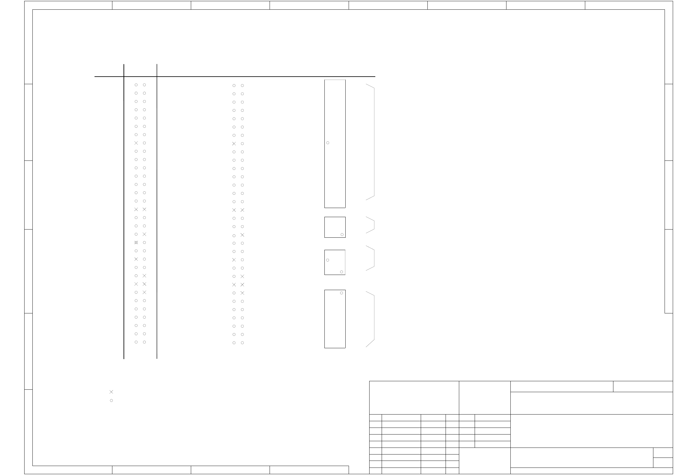
2 Circuit Diagrams 93
00344266-010301TD3 Terminal panel, lefthand side
XX
1
1
2
(ye/gn)
acc. to BV 00343603, sh. 2
Ground connection
78
X
A4
100mm
1
1
Cable duct 65x30 l=325mm
Scotchcal 3698-E
X2kc
Nut DIN 439
Contact washer SN 70093
Screw
Cable duct 65x30 l=400mm
12
A3 A2
Font size: 2.5mm, material
X
A
7
3
4
5
EA
X1kd
Cable duct 65x46 l=425mm
2
2
21
13
Note 1:
B
C
D
C: Ground plate
1
A
X
acc. to SN 01007
6
A
A1
5
A
X2kd X2kc
5
A
X7kg
4
5
1
19
X1kb X1ka
X2kb
9
X2kd X2kc
X2kb X2ka
14
15
16
16
17
40
20
Annular cable lug
8
CCCC = Series number
X2kg
2
22
X5ki X6ki
4
X2ki
X3kg
X1ke
4
X7kh
X2kk
A5
500mm
XX
X
6
X211
3
35mm
78
1
30mm
4
E
D
C
B
3
6
SIEMENS AUT 5
00344266-01
AA-BBBB-CCCC
2
4
X
4
X2ka
X2ke
1
7
8
8
6
6
17
18
18
X2kf
8
9
10
E
X5kg
acc. to SN 37040
END
SMD Placement System
12
3
3
E
FF
B
0V
X6kg
X2kf
3
VA-F-510-001 guideline
(Note: XXX means to knock out three lugs from the cable duct)
22
X2ke
3
23
24
Cable duct 65x46 l=425mm
0V
0V
0V
0V
0V
0V
3
3
X7ki
XXXXX
Cable duct lengths +/- 5mm
XX
X2kd
X2kb
5
X1kc
X212
6
7
11
have to be applied:
A: Identification label
B: Inspection label
1
X2kf
X
45
Split ring DIN 7980
X
Washer DIN 125
C
Cable duct 65x30 l=425mm
3
20
20
21
10
X
60mm 110mm
XXXX
Nut DIN 439
2
X4kg
X2ka
X3kh
420mm
The following labels
Assembly inscription acc. to
30mm
3
3
3
50mm
X1kf
X2kh X1kh
X210
X3ki X4ki
(Note: X means to knock out one lug from the cable duct)
X
130mm
X1ki
(Color: A1 RAL 9006)
AA = Manufacturer/location
BBBB = Datum (Jahr/Monat/Tag)
4
4
10
10
10
SIPLACE 80F4/F6/F5-HM
4
(Note: X means to knock out one lug from the cable duct)
X1kg
Product status
Function status
01
03
01
Leh
Deu
Leh
3
A6
X2ke
E
19
X
XX
PL EA1 E5
00344266-010301TD3
Terminal panel, lefthand side
#
*
Tuth
14.04.99
05.10.98
14.04.99
05.10.98
Document status
=
Datum
Gepr.
Norm
Bearb.
Sheet
Urspr. Ers. f. Ers. d.NameDatumAenderungZustand
SIEMENS AG
Sh.
+
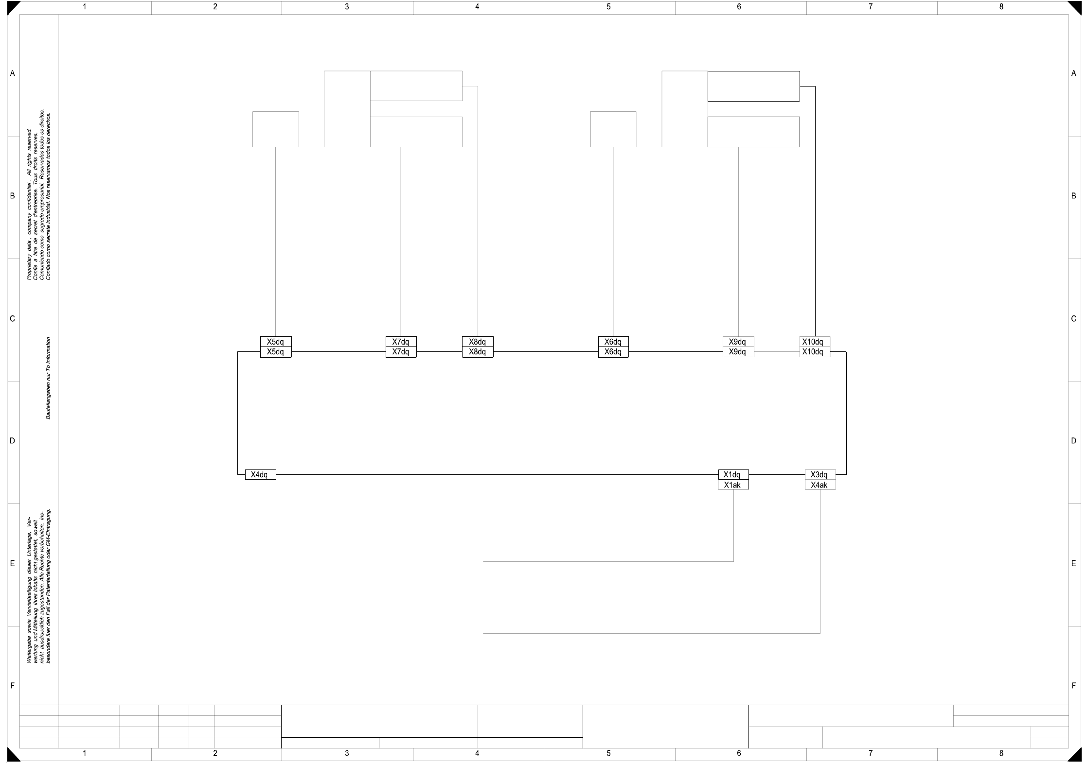
2 Circuit Diagrams 94
00328647-010101LD3 Tape cutter, max. tape height 15 mm
SIPLACE
00313400
00322071 / 00322072
Tek
Tek
01.
01.
01.
10.07.97
10.07.97
25.11.97
10.07.1997
Eschenweck
#
00328647-010101LD3
PL EA1 E2
Tek
=
Datum
Gepr.
Norm
Bearb.
Blatt
Urspr. Ers. f. Ers. d.
NameDatumAenderungZustand
SIEMENS AG
Bl.
+
1
1
Product status
Doc. status
Function status
To interface
Tape cutter
Max. tape height: 15 mm
Cable: power supply unit - tape cutter
Cable: interface (left / right) - tape cutter
component supply
00322063 / 00322064
left / right
To
power supply / T2
00300243
(2x24VAC / 0V)
(dq)
00329699
Control board, tape cutter
Cable: control board tape cutter - valve
00332901
00332900
Proximity switch with cable for tape cutter II
Proximity switch with cable for tape cutter II
00332900
Cable: control board tape cutter - valve
00332901
Proximity switch with cable for tape cutter I
00332899
00332899
Proximity switch with cable for tape cutter I
Left
valve
cylinder
Left
Front
proximity switch
Rear
proximity switch
Front
proximity switch
proximity switch
Rear
Right
cylinder
valve
Right
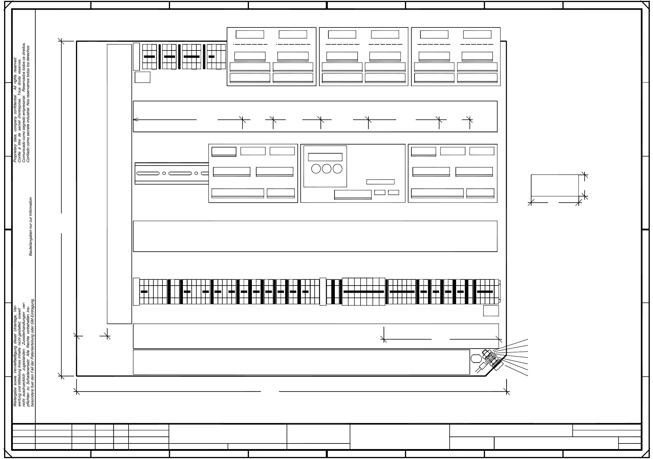
2 Circuit Diagrams 95
00331465-020101TD3 Control unit, single conveyor (viewed from the front/back)
assemblies overview (Sh. 1 of 2)
27.03.1997
Haas
1.
Ha
Ha
1. 27.03.97
27.03.97
1. 27.03.97
Ha
80S4/DCTA/
33146511_d
(assemblies overview)
(viewed from the front/back)
Control unit, single conveyor
00331465-020101TD3
F
1234
E
D
Massstab
Siemens AG
AUT 5
Zust Aenderung Datum Name
Gepr.
Norm
Beab.
Datum
Bl.
Bl.
D
C
B
A
1234
C
B
8567
A
Function status
Doc. status
SMD Placement System Siplace 80S/F/G
1
2
Product status
Mat.-Nr.:
CAD-Datei:
331465-01
n.c.
Cut off pin
Coding pin
32
31
29
30
24
26
27
28
25
22
23
20
21
Motor center conv.2
Motor input conv.1
Motor output conv.1
Motor center conv.1
+30V
GND 30V
Motor center conv.2
Motor input conv.1
Motor output conv.1
GND 30V
Motor center conv.1
+30V
+30V
n.c.
30V
n.c.
n.c.
n.c.
5V
n.c.
n.c.
n.c.
T
n.c.
n.c.
n.c.
15
18
19
16
17
13
14
12
11
6
10
9
8
7
5
4
3
2
1
Pin b a
Motor input conv.2
Motor output conv.2
Input conv. 2 fast
Output conv. 2 fast
Input conv. 1 fast
Center conv. 1 fast
Center conv. 2 fast
Output conv. 1 fast
Light barr., center conv.2
Light barr., output conv. 1
Light barr., input conv. 1
Light barr. center conv. 1
Light barr. input conv. 2
Light barr. output conv. 2
Motor input conv.2
Motor output conv.2
Input conv. 2 slow
n.c.
n.c.
n.c.
TT
Input conv. 1 slow
Center conv. 1 slow
Output conv. 1 slow
Center conv. 2 slow
Output conv. 2 slow
T
30V
n.c.
30V
T
30V
30V
30V
6x half-bridge board, digital
30V 30V
X4C
13
14
87
1
2
X5C
3
1
4
2
X3C
1
5
29
6
2
30
15
16
X2C
12
motor distributor
I/O terminal boards
00326067-XX
Round cable
voltage supply
14-pole flat ribbon cable
00326063-XX
6-pole flat ribbon cable
to conversion board
00326067-XX
to conversion board
30-pole flat ribbon cable
00331297-XX