46230809.pdf - 第19页
Page 19 TECHNICAL PUBLICATIONS Dual Rotary Positioning Assembly - BHS T46230809 Rev .C This Document Supports Assembly 46230809 Due to the tolerance build up, interference may be felt when inserting and removing the pins…
Page 18
TECHNICAL PUBLICATIONS
T46230809 Rev. C Dual Rotary Positioning Assembly - BHS
This Document Supports Assembly 46230809
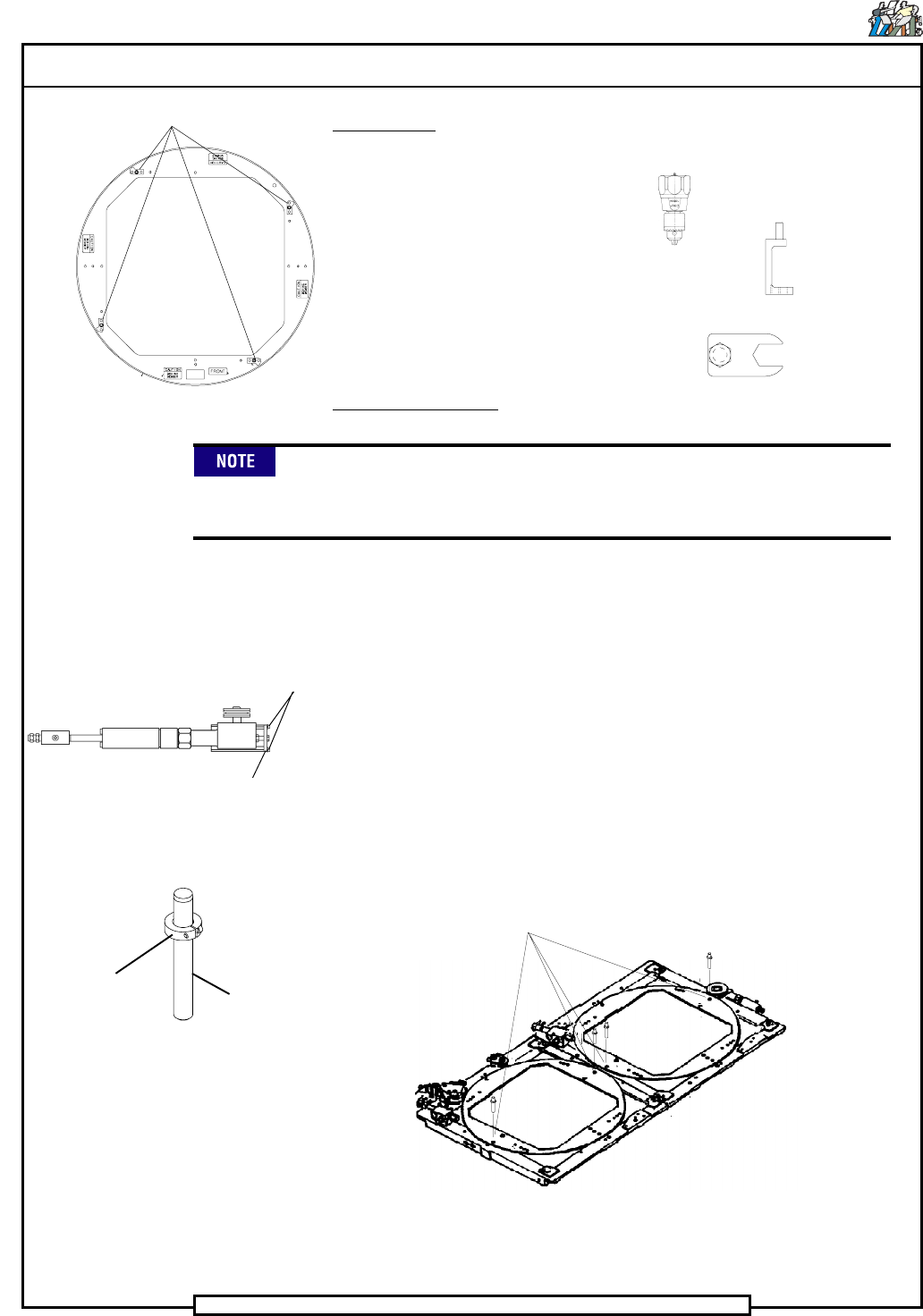
Special Tools:
Torque Wrench (in./lbs.)
Torque Gage (in./oz.) (46808001)
(Waters Mfg. model 651C-30)
Torque Adapter (45081601) (High profile guide wheels)
Dowel pins (1/4 x 2) (80010109) with collars (18333000)
Wrench (46758401) (Low profile guide wheels)
Adjustment Procedure:
Depending on the machine configuration, covers and/or assembly
components will have to be removed to allow access to the guide
wheels and drive assembly.
1. Remove the four stop blocks from the rotary disk
2. Remove the two socket head cap screws from the stop plate on the
drive assembly.
3. Remove the stop plate from the drive assembly to remove the drive
wheel pressure on the rotary disk.
4. Assemble the locator pin assemblies using dowel pins and collar
clamps.
5. Insert the locator pin assemblies through the locator holes in the rotary
table and into the locator holes in the X axis table as shown.
Rotary Disk Assembly
STOP BLOCKS
Rotary Disk Drive Assembly
SOCKET HEAD
CAP SCREWS
STOP
PLATE
Locator Pin Assembly
DOWEL PIN
COLLAR
CLAMP
LOCATOR
HOLES
Page 19
TECHNICAL PUBLICATIONS
Dual Rotary Positioning Assembly - BHS T46230809 Rev.C
This Document Supports Assembly 46230809
Due to the tolerance build up, interference may be felt when inserting
and removing the pins. This is normal and in no way means the table is
not square. If the pins can not be inserted into the holes, the disk is not
square. Some resistance may be encountered when fitting the pins into
the holes, but the resistance should never require the assistance of a
tool to remove the pins from the X axis frame.
6. If the pins can be inserted into the locator holes, proceed to step 20 to
adjust the lock assembly. If the pins can not be inserted into the locator
holes, proceed as follows.
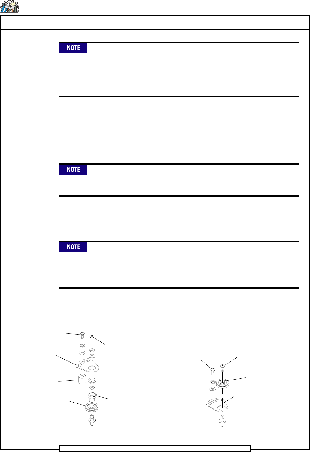
7. Loosen the button head cap screw securing the locking bracket at each
of the four guide wheel assemblies.
Machines with Board Handling System have two styles of rotary disk
guide wheels. Two are high profile as used on machines without board
handling and two are low profile. Refer to the illustration below.
8. At each of the four guide wheel assemblies, loosen the button head cap
screw that secures the guide wheel bushing adapter and/or guide wheel
with bushing enough to allow them to turn.
The guide wheel bushing adapter/guide wheel with bushing is an
eccentric. Turning them in a counterclockwise direction increases the
amount of resistance between the rotary disk and the guide wheel.
Turning them in a clockwise direction decreases the amount of
resistance between the guide wheel and the rotary disk.
9. Using the locking bracket, rotate each guide wheel bushing adapter
and/or guide wheel with bushing in a clockwise direction, to release
pressure on the rotary disk.
GUIDE WHEEL
BUSHING
ADAPTER
GUIDE
WHEEL
LOCKING
BRACKET
SPACER
HIGH PROFILE
BUTTON HEAD
CAP SCREW
LOW PROFILE
BUTTON HEAD
CAP SCREW
LOCKING
BRACKET
GUIDE WHEEL
WITH BUSHING
BUTTON HEAD
CAP SCREW
BUTTON HEAD
CAP SCREW
Page 20
TECHNICAL PUBLICATIONS
T46230809 Rev. C Dual Rotary Positioning Assembly - BHS
This Document Supports Assembly 46230809
10. Manually position the rotary disk so the FRONT label on the rotary
disk is located at the front of the machine.
11. Align the two .25 inch (6,4mm) locating holes in the rotary disk with
the two .25 inch (6,4mm) locating holes in the top of the X axis frame.
The rotary disk is centered between the four guide wheels by applying
equal pressure from all four guide wheels. When adjusting the guide
wheels, adjust in diagonal pairs. Adjust one diagonal pair of guide
wheels, then adjust the other diagonal pair of guide wheels in the same
manner.
The bushing adapters should be tightened counter-clockwise.
Excessive force in a clockwise direction could cause the rotary disk to
deform.
Work with the bushing adapters in pairs. Continuously check the two
locator pin assemblies after each bushing adapter pair adjustment. If
the locator pin assemblies start to resist removal, the bushing adapter
has been adjusted too tight against the rotary disk.
12. Preload all the guide wheel bushing adapters in a counterclockwise di-
rection to just remove the vertical spacing between the rotary disk and
guide wheels. Check this by physically moving the rotary disk up and
down.
13. Start with the guide wheel mounted on the front left side of the X axis
frame assembly. Align the guide wheel with the rotary disc then adjust
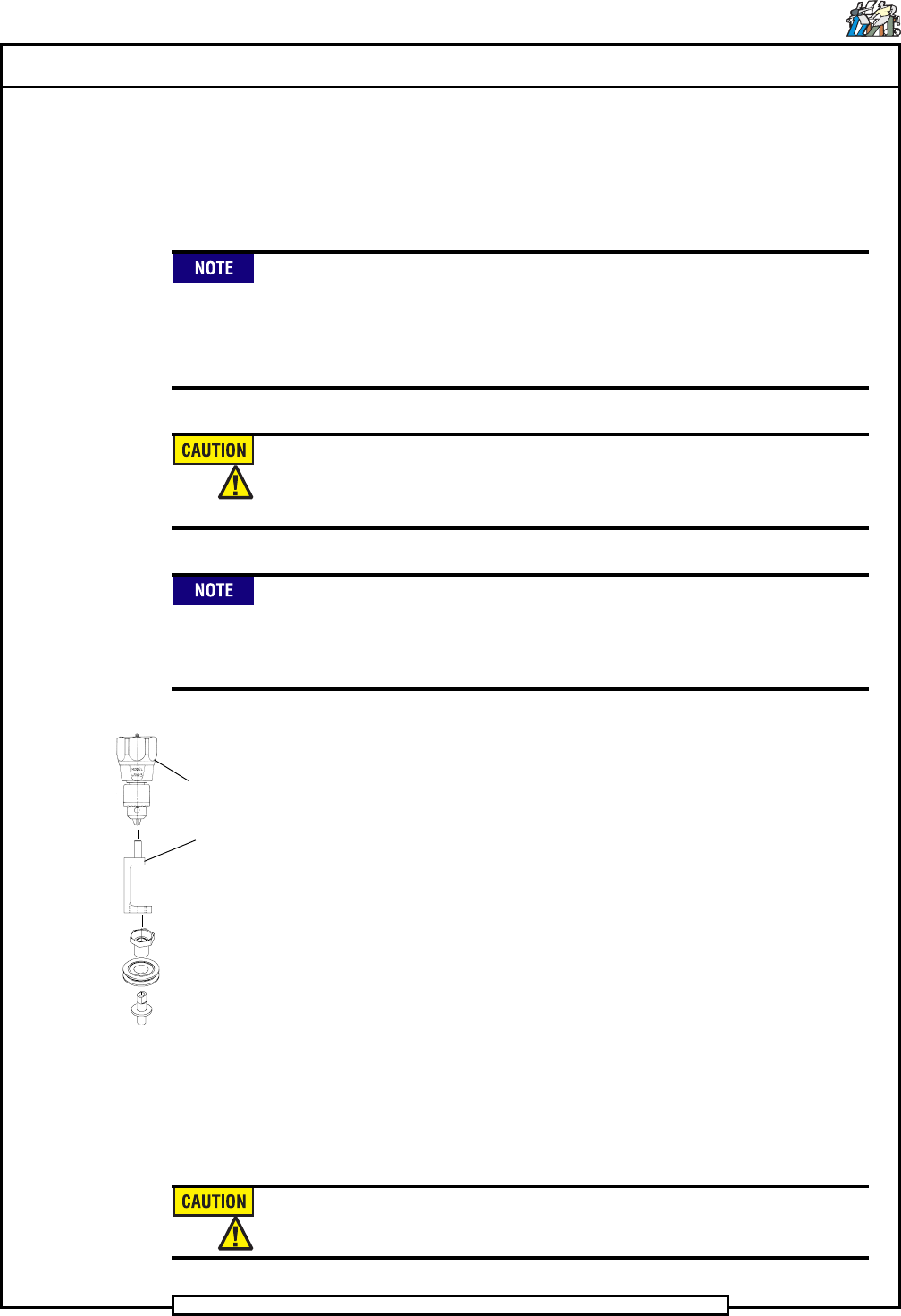
the bushing adapter in a counterclockwise direction. Using the inch/oz.
torque gage and torque adapter (high profile) or inch/oz. torque gage,
torque adapter and wrench (low profile), tighten the bushing adapter to
14 inch ounces (98,86Nm).
14. While holding the torque gage at 14 inch ounces, tighten the button
head screw to approximately 40 - 45 inch pounds to secure the adjust-
ment of the bushing adapter.
15. Repeat the adjustment procedure in steps 13 and 14 for the guide wheel
mounted on the rear right side of the X axis frame assembly.
16. Perform steps 13 and 14 for the remaining pair of guide wheels.
To avoid stripping the aluminum tapped holes, do not over tighten the
screws securing the adapter bushings.
HIGH PROFILE
TORQUE
GAGE
TORQUE
ADAPTER