46230809.pdf - 第22页
Page 22 TECHNICAL PUBLICATIONS T46230809 Rev . C Dual Rotary Positioning Assembly - BHS This Document Supports Assembly 46230809 31. Reposition the rotary disk drive assembly stop plate and secure it in place with the so…
Page 21
TECHNICAL PUBLICATIONS
Dual Rotary Positioning Assembly - BHS T46230809 Rev.C
This Document Supports Assembly 46230809
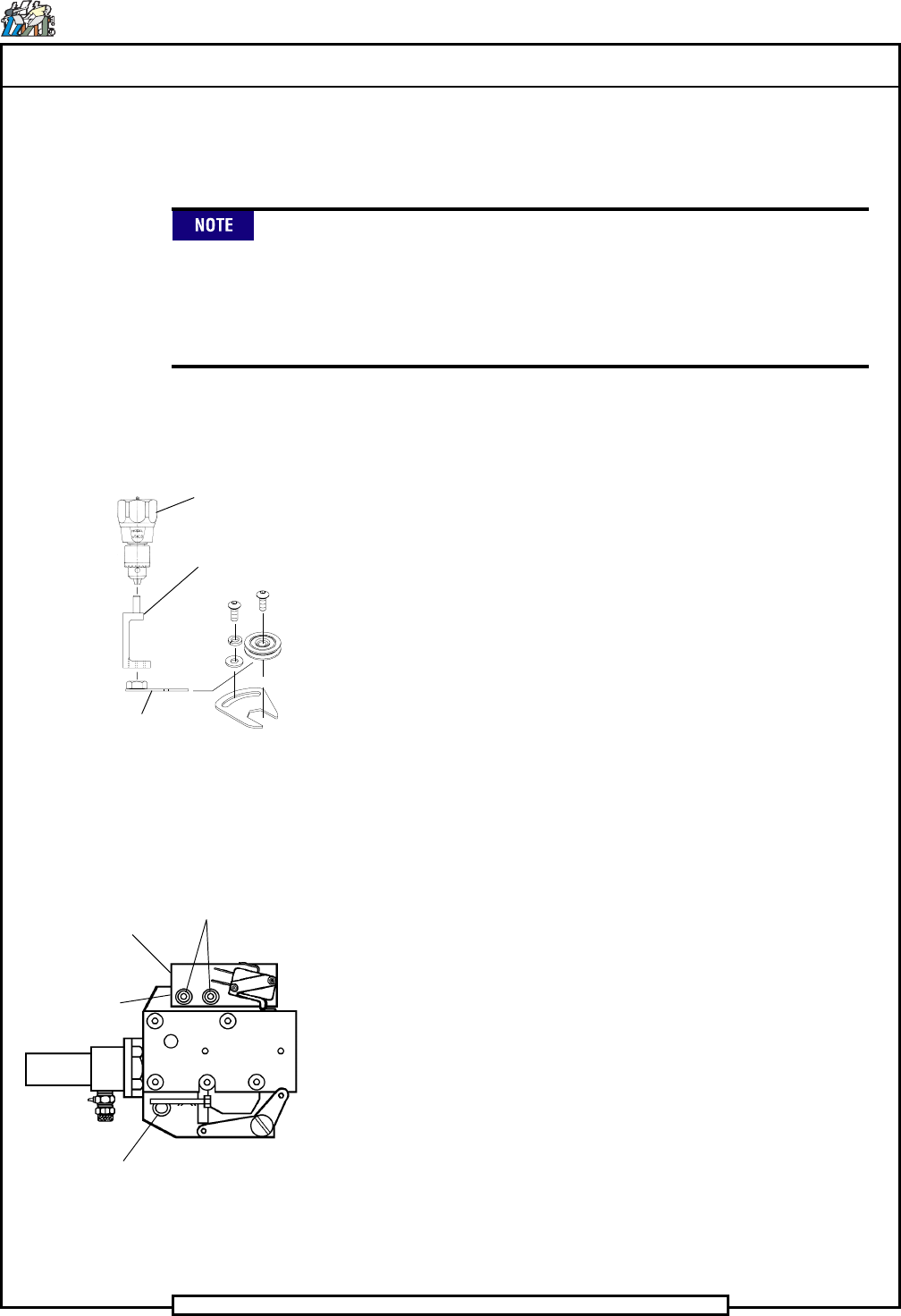
LOW PROFILE
WRENCH
TORQUE
ADAPTER
TORQUE
GAGE
SOCKET HEAD
CAP SCREW
SOCKET HEAD
CAP SCREW
(LOCATED UNDER
THE
BRACKET)
SWITCH
BRACKET
Rotary Disk Lock Assembly
SOCKET HEAD
CAP SCREWS
17. Check the locator pin assemblies. If the locator pins do not slide into
and out of the locator holes, the bushing adapter has been adjusted too
tightly against the rotary disk.
Due to the tolerance build up, interference may be felt when inserting
and removing the pins. This is normal and in no way means the table is
not square. If the pins can not be inserted into the holes, the disk is not
square. Some resistance may be encountered when fitting the pins into
the holes, but the resistance should never require the assistance of a
tool to remove the pins from the X axis frame.
18. Remove the locator pins and rotate the rotary disk one full revolution
to settle in the guide wheels.
19. Reinsert the locator pins into the locator holes and check that the loca-
tor pins slide into and out of the holes. If they do not, repeat steps 9
through 18 until the locator pins fit properly.
20. Install the four stop blocks on the rotary disk assembly.
21. Remove the screws that secure the switch bracket on the lock assembly
and remove the switch bracket.
22. Loosen the socket head cap screws shown that secure the lock assem-
bly to allow adjustment of the lock assembly.
23. Insert the locator pins into the locator holes.
24. Manually move the lock assembly until the locator pins slide with even
force into the alignment holes.
25. In a diagonal pattern, tighten the socket head cap screws which secure
the lock assembly, 1/8 of one revolution per screw until the screws are
fully tightened.
26. With the locator pins removed, disengage the stop block from the lock
assembly then turn the rotary disk to securely engage the rotary disk
stop block into the lock assembly.
27. Check that the locator pins slide into and out of the locator holes.
28. If the locator pins do not slide into and out of the locator holes, repeat
steps 22 through 27 until they fit properly.
29. Replace the switch and bracket on the lock assembly and secure it in
position with the socket head cap screws.
30. Adjust the switch on the lock assembly so the switch actuator is de-
pressed.
Page 22
TECHNICAL PUBLICATIONS
T46230809 Rev. C Dual Rotary Positioning Assembly - BHS
This Document Supports Assembly 46230809
31. Reposition the rotary disk drive assembly stop plate and secure it in
place with the socket head cap screws. Ensure the rotary disk is cen-
tered in the V-groove of the rotary disk drive assembly drive wheel.
32. Check that the locator pins slide into and out of the locator holes.
33. Remove the locator pins from the rotary table locator holes.
34. Ensure the locking brackets do not extend over the rotary disk then
tighten the button head cap screws securing each locking bracket in po-
sition.
35. Replace any covers and/or assembly components that were removed to
allow access to the guide wheel assemblies.
End of procedure.
X- Y Axes Belt Tension Specification and
Adjustment Procedure
Purpose:
The correct belt tension for the X and Y axis drive is critical to ensure opti-
mal machine performance and long motor life. If the X and Y belts are under
tensioned, the positioning system will not correctly pull into position thereby
decreasing insertion reliability. If the belts are over tensioned, the bearing
life of the motors will be decreased. The X and Y axes have a built in belt
tensioning feature.
Because new belts stretch after approximately 150 hours of machine
operation, the belt tension must be reset after 150 hours of machine
operation.
Specification
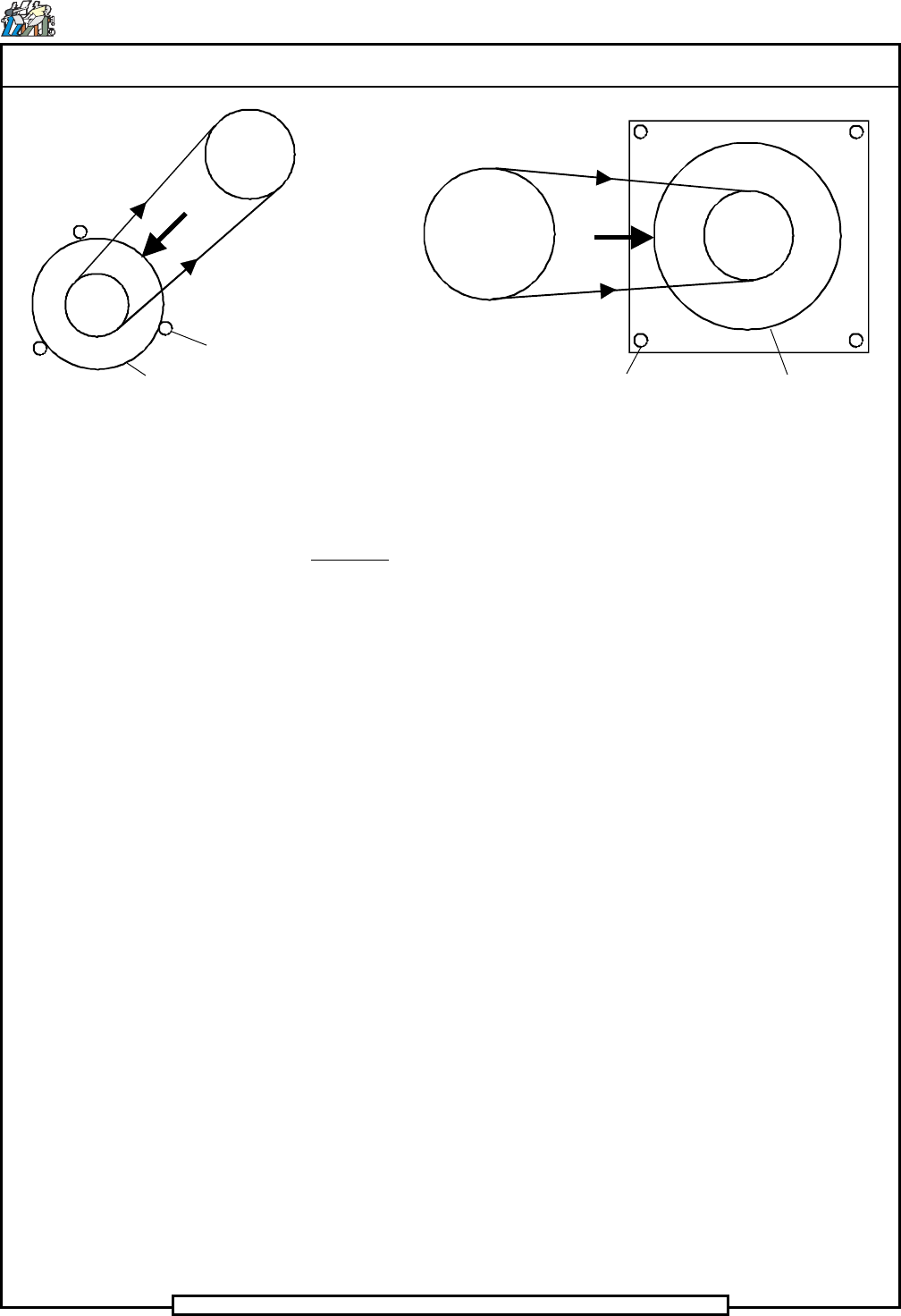
The static tension (T) of the belt and the static force (F) required on the motor
to attain this tension is as follows. A built in spring mechanism applies the
required static force (F) to the motor.
T = 17.5 lbs ± 2.5 lbs (78N ± 11N) (per side)
F = 35 lbs ± 5 lbs (156N ± 22N)
Page 23
TECHNICAL PUBLICATIONS
Dual Rotary Positioning Assembly - BHS T46230809 Rev.C
This Document Supports Assembly 46230809
Adjustment Procedure
Procedure:
1. Ensure the belt is correctly seated into both pulleys by rotating the pul-
leys several rotations. This can be accomplished by moving the appro-
priate axis by hand.
2. Loosen the motor mounting screws and allow the spring mechanism in
the mounting plate to apply a force against the side of the motor. The
force is applied in the direction shown, away from the lead screw pul-
ley and along the line between the centers of the pulleys.
3. With the force applied, again ensure the belt is correctly seated into
both pulleys by rotating the pulleys several rotations. This can be ac-
complished by moving the appropriate axis by hand.
4. While the spring mechanism maintains the required force against the
side of the motor, tighten the motor mounting screws .
End of procedure.
X-Axis Motor Y-Axis Motor
Motor
Motor Mounting Screws
Motor
Motor Mounting Screws
F
F
T
T
T
T