46230809.pdf - 第26页
Page 26 TECHNICAL PUBLICATIONS T46230809 Rev . C Dual Rotary Positioning Assembly - BHS This Document Supports Assembly 46230809 10. In the Zero - Table Y Axis dialog screen select Default then OK The Manual Diagnostics …
Page 25
TECHNICAL PUBLICATIONS
Dual Rotary Positioning Assembly - BHS T46230809 Rev.C
This Document Supports Assembly 46230809
4. Place the set up template on the rotary table beneath head 1 and secure
it in position using the locator pins and thumb screws.
5. Activate the IM Diagnostics as follows. Refer to the IM-UPS and IM
Diagnostics documentation for specific details relating to the operation
of the machine terminal.
Select the IM Diagnostics icon.
When the machine is in the IM Diagnostics function, power is provided
to the machine. Exercise caution when performing the following
procedures to avoid Injury to personnel and equipment.
6. After the IM Diagnostics has completed its initialization, select the fol-
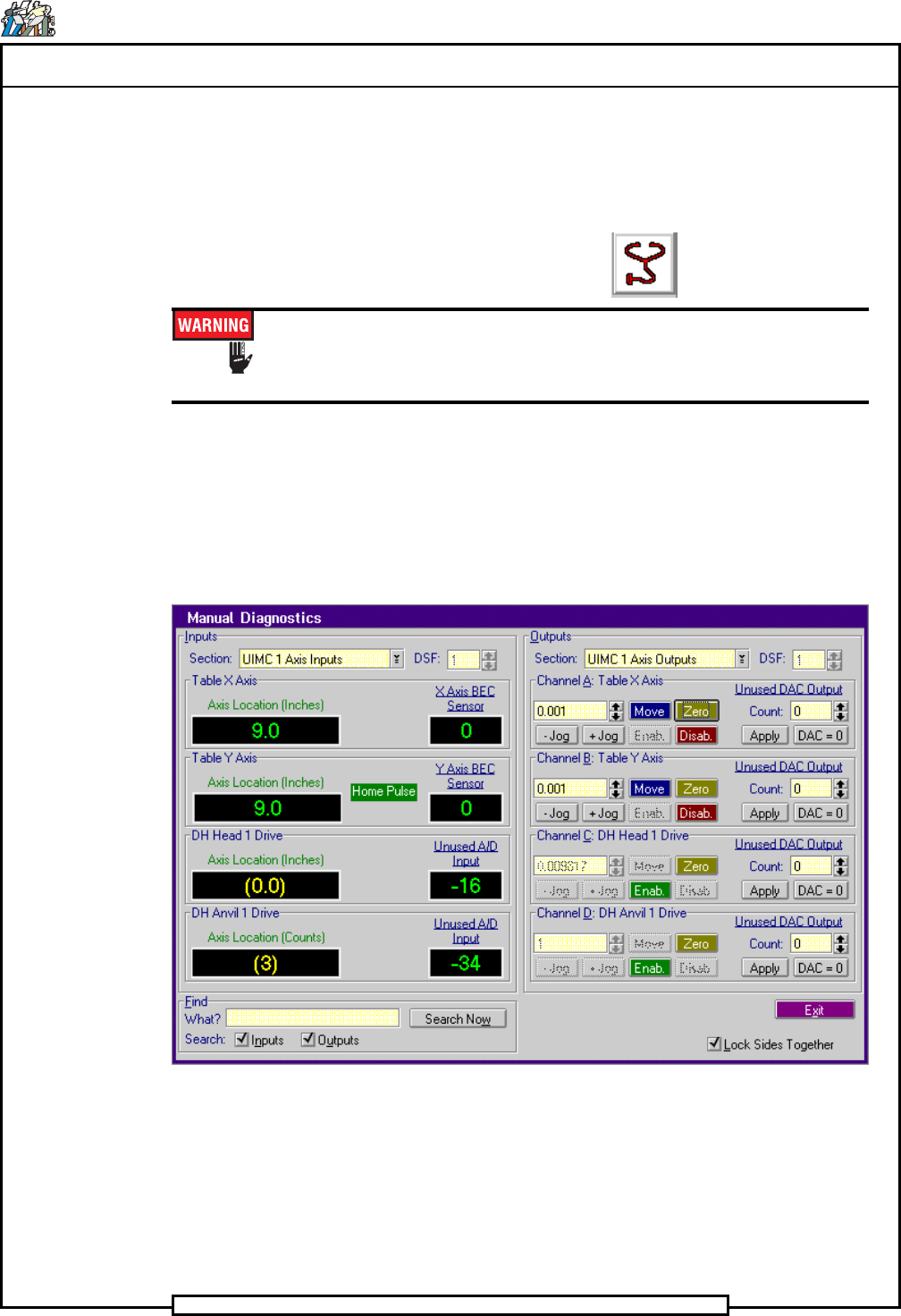
lowing. Diagnostics>Manual Diagnostics
The Manual Diagnostics screen is displayed
7. In the Outputs side of the Manual Diagnostics screen, select the follow-
ing. Section>UIMC 1 Axis Outputs
8. Palm the machine up and push the INTLK RESET push button.
9. Select Channel B: Table Y Axis>Zero
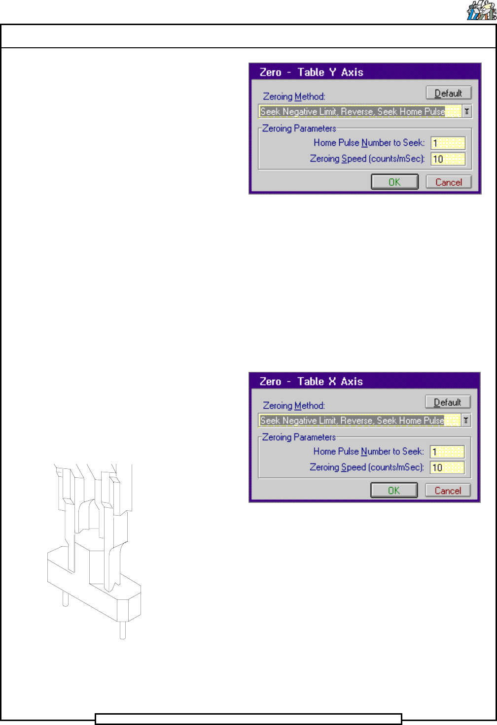
The Zero - Table Y Axis dialog screen is displayed.
Page 26
TECHNICAL PUBLICATIONS
T46230809 Rev. C Dual Rotary Positioning Assembly - BHS
This Document Supports Assembly 46230809
10. In the Zero - Table Y Axis dialog screen select Default then OK
The Manual Diagnostics screen is displayed.
- In the Channel B: Table Y Axis increment box, click on the up
or down ¯ arrows until 1.0 appears in the increment box.
- Click on the + Jog button until the Axis Location for the Table
Y Axis indicator in the Input side of the screen reads 9.0.
11. Select Channel A: Table X Axis>Zero
The Zero - Table X Axis dialog screen is displayed.
12. In the Zero - Table X Axis dialog screen select Default then OK
The Manual Diagnostics screen is displayed.
- In the Channel A: Table X Axis increment box, click on the up
or down ¯ arrows until 1.0 appears in the increment box.
- Click on the + Jog button until the Axis Location for the Table
X Axis indicator in the Input side of the screen reads 9.0.
13. In the Outputs side of the Manual Diagnostics screen, select the follow-
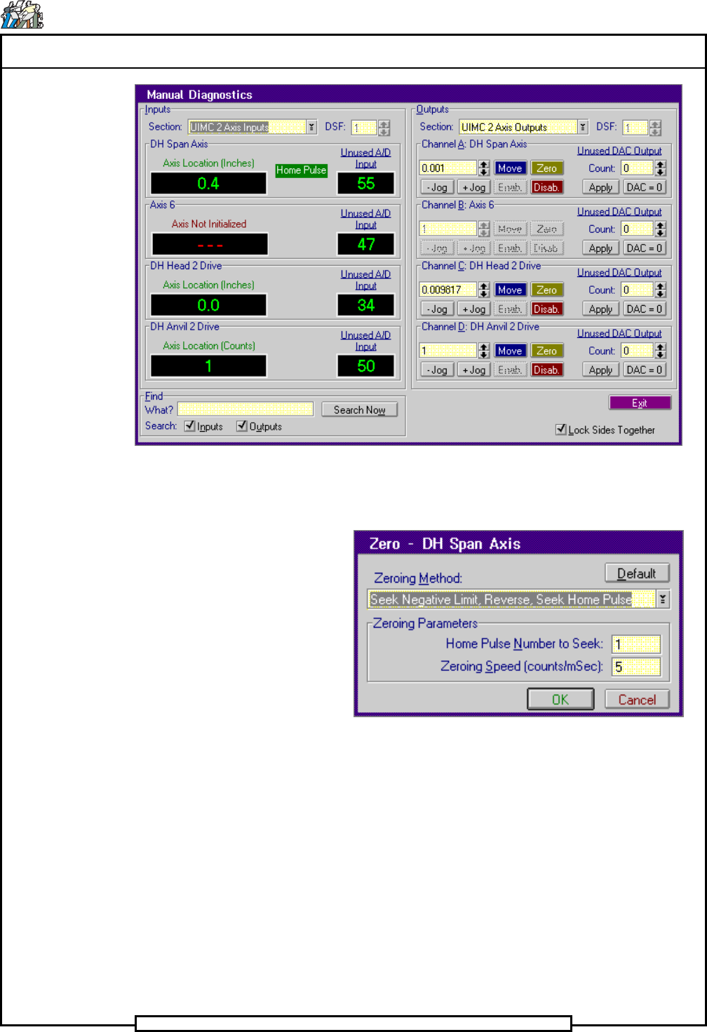
ing. Section>UIMC 2 Axis Outputs
Set up Tool in Outside Formers
Page 27
TECHNICAL PUBLICATIONS
Dual Rotary Positioning Assembly - BHS T46230809 Rev.C
This Document Supports Assembly 46230809
14. Select Channel A: DH Span Axis>Zero
The Zero - DH Span Axis dialog screen is displayed.
15. In the Zero - DH Span Axis dialog screen select Default then OK
The Manual Diagnostics screen is displayed.
- In the Channel A: DH Span Axis increment box, click on the up
or down ¯ arrows until 0.1 appears in the increment box.
- Click on the + Jog button until the Axis Location for the Table
Y Axis indicator in the Input side of the screen reads 0.4.
16. Set the X and Y axis circuit breakers, 2CB and 3CB, to the off position.