46230809.pdf - 第31页
Page 31 TECHNICAL PUBLICATIONS Dual Rotary Positioning Assembly - BHS T46230809 Rev .C This Document Supports Assembly 46230809 - In the Channel A: Table X Axis increment box, click on the up or down ¯ arrows until unt…
Page 30
TECHNICAL P UBLICATIONS
T46230809 Rev. C Dual Rotary Positioning Assembly - BHS
This Document Supports Assembly 46230809
8. Proceed as follows for each specific limit adjustment.
When jogging an axis, the RATE switch settings are only calibrated in
inch increments. For machines operating in metric dimensioning, refer
to the LOCATION Set commands for actual axis position.
X Axis Negative Limit
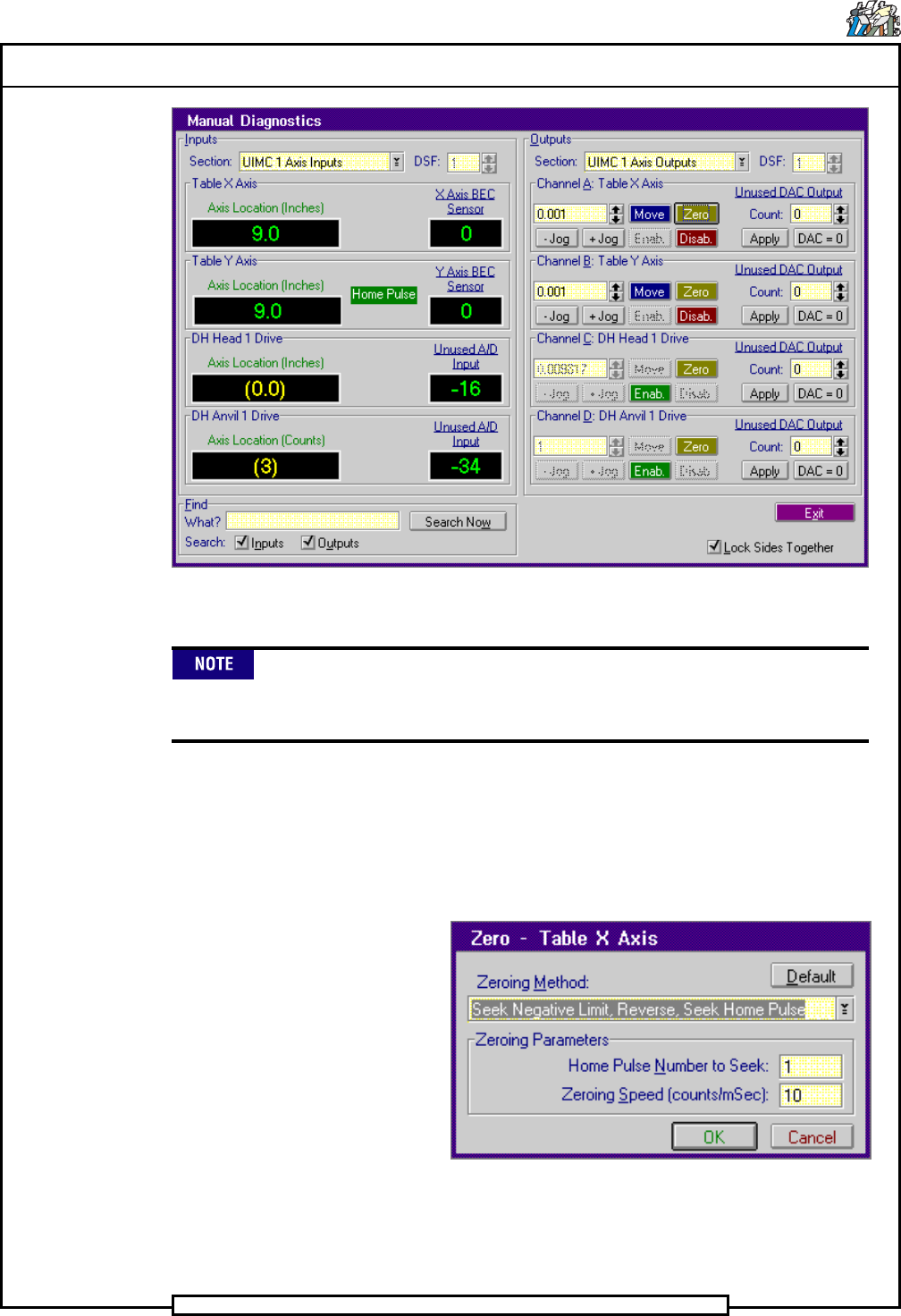
1. Select Channel A: Table X Axis>Zero
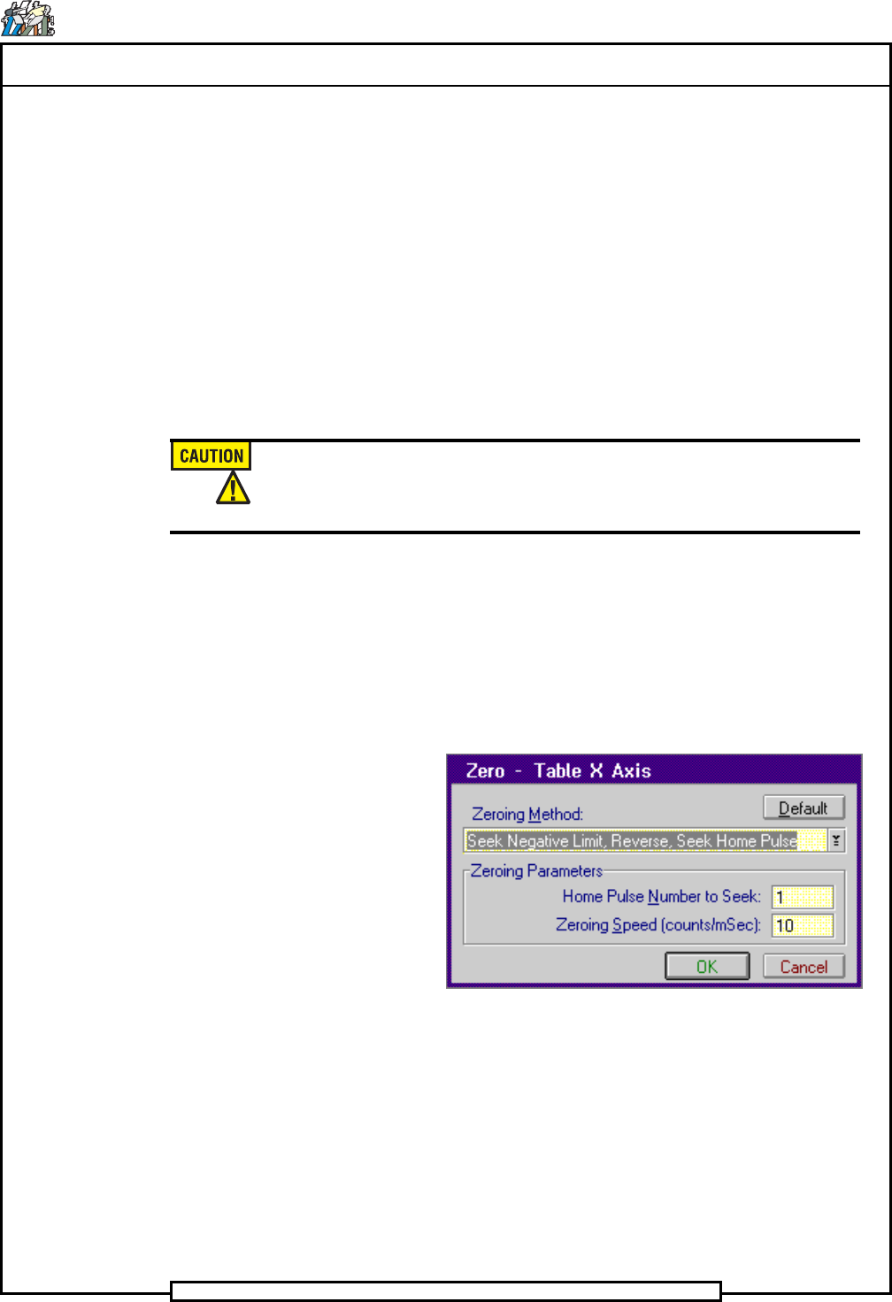
The Zero - Table X Axis dialog screen is displayed.
2. In the Zero - Table X Axis dialog screen select Default then OK to
move the X axis to the 0.0 position.
The Manual Diagnostics screen is displayed.
Page 31
TECHNICAL PUBLICATIONS
Dual Rotary Positioning Assembly - BHS T46230809 Rev.C
This Document Supports Assembly 46230809
- In the Channel A: Table X Axis increment box, click on the up
or down ¯ arrows until until 0.010 appears in the increment box.
3. Click on the - Jog button until one of the following occurs.
a. The position of the X-axis in the Axis Location display is
between -0.080 and -0.150. In this case, move the limit switch
block until the negative limit just actuates, then secure the
actuator. Zero the axis and jog to the limit to verify the correct
limit position.
b. A negative hard limit occurs, the Hard Limit indicator is
displayed. In this case, move the actuator block slightly away
from the limit switch then repeat steps 1 through 3.
Do not move the negative limit actuator excessively. Excessive
movement will disrupt the zero position of the axis and may require axis
encoder adjustment.
End of procedure.
X Axis Positive Limit
1. Select Channel A: Table X Axis>Zero
The Zero - Table X Axis dialog screen is displayed.
2. In the Zero - Table X Axis dialog screen select Default then OK to
move the X axis to the 0.0 position.
The Manual Diagnostics screen is displayed.
- In the Channel A: Table X Axis increment box, click on the up
or down ¯ arrows until 1.0 appears in the increment box.
3. Click on the + Jog button until the Axis Location display reads 18.0
inches.
Page 32
TECHNICAL P UBLICATIONS
T46230809 Rev. C Dual Rotary Positioning Assembly - BHS
This Document Supports Assembly 46230809
4. In the Channel A: Table X Axis increment box, click on the up or
down ¯ arrows until 0.010 appears in the increment box.
5. Click on the + Jog button until one of the following occurs.
a. The position of the X-axis in the Axis Location display is
between 18.080 and 18.150. In this case, move the limit switch
block until the positive limit just actuates, then secure the
actuator. Zero the axis and jog to the limit to verify the correct
limit position.
b. A positive hard limit occurs, the Hard Limit indicator is
displayed. In this case, move the actuator block away from the
limit switch then repeat steps 1 through 5.
End of procedure.
Y Axis Negative Limit
1. Select Channel B: Table Y Axis>Zero
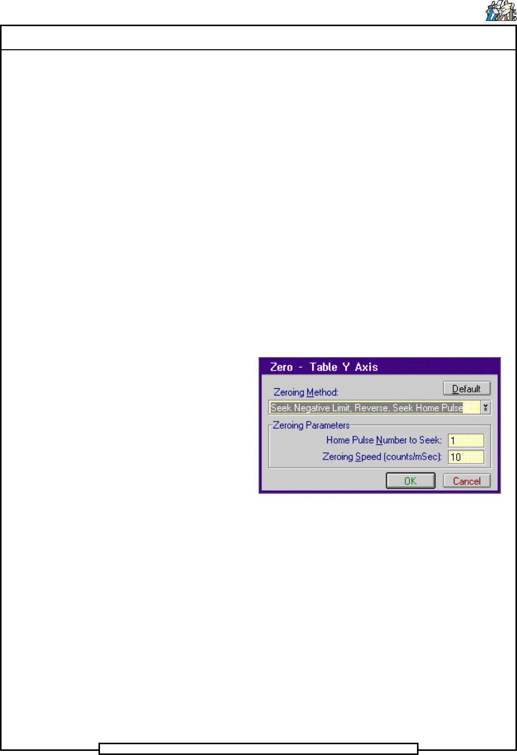
The Zero - Table Y Axis dialog screen is displayed.
2. In the Zero - Table Y Axis dialog screen select Default then OK
The Manual Diagnostics screen is displayed.
- In the Channel B: Table Y Axis increment box, click on the up
or down ¯ arrows until 0.010 appears in the increment box.
3. Click on the - Jog button until one of the following occurs.
a. The position of the Y-axis in the Axis Location display is
between -0.080 and -0.150. In this case, move the limit switch
block until the negative limit just actuates, then secure the
actuator. Zero the axis and jog to the limit to verify the correct
limit position.
b. A negative hard limit occurs, the Hard Limit indicator is
displayed. In this case, move the actuator block away from the
limit switch then repeat steps 1 through 3.