46230809.pdf - 第40页
Page 40 TECHNICAL P UBLICATIONS T46230809 Rev . C Dual Rotary Positioning Assembly - BHS This Document Supports Assembly 46230809 13. Using the socket head screws, install the plate retainer and dust bellow to the bearin…
Page 39
TECHNICAL PUBLICATIONS
Dual Rotary Positioning Assembly - BHS T46230809 Rev.C
This Document Supports Assembly 46230809
3. Place the puller support over the threaded end of the bolt then install
the nut and washer onto the bolt until the washer is against the outer
surface of the puller support.
4. Hold the bolt head from turning and turn the nut until the pilot bottoms
out on the inside of the puller support.
5. While holding the bolt head from turning, remove the nut from the bolt
then remove the remaining parts of the board assembly tool.
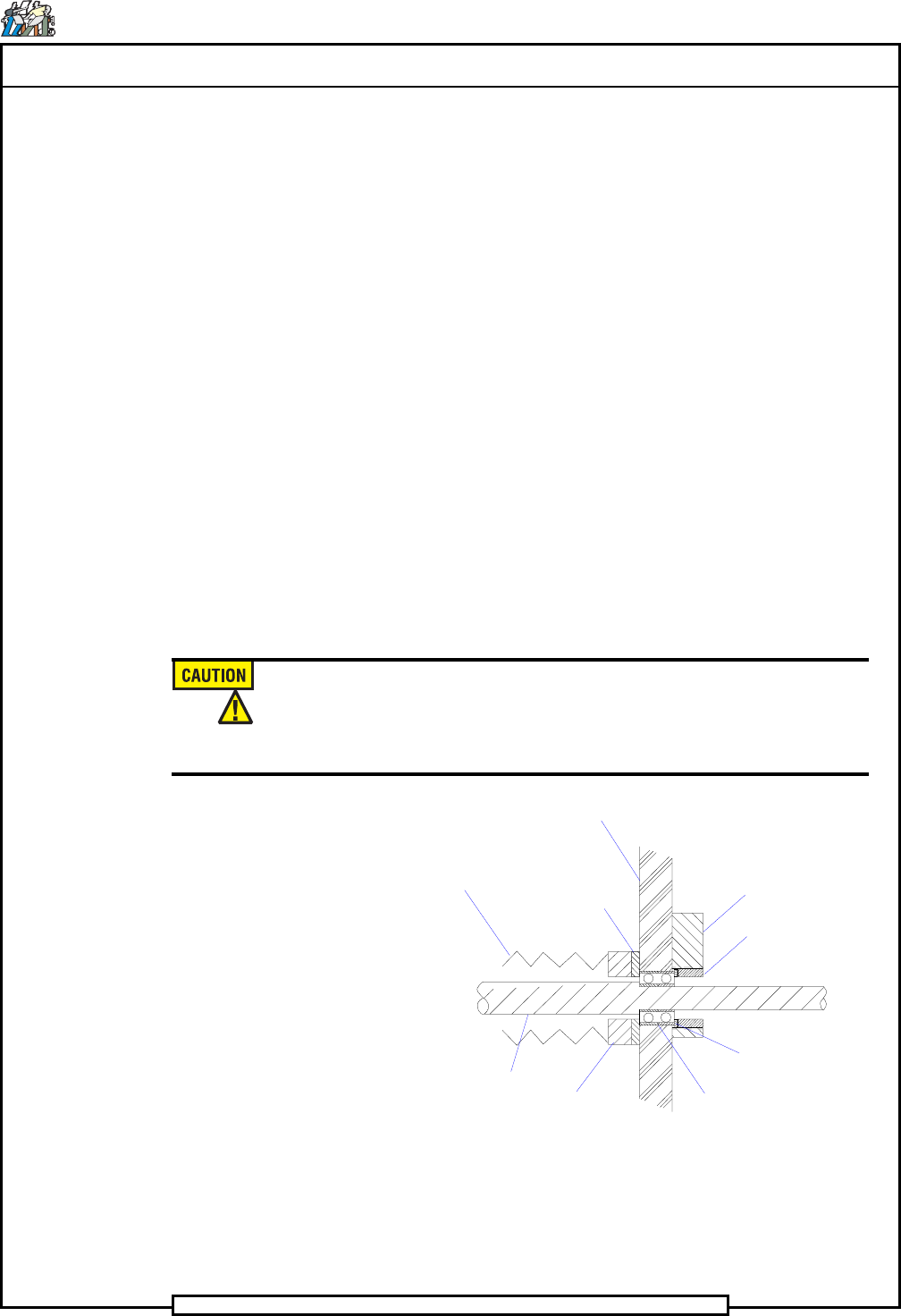
6. Using the flat head screws, install the bearing retainer and bearing
washer to the inside surface of the C-frame.
7. Using the socket head screws, install the bearing plate to the outer sur-
face of the C-frame.
8. Install the plug washer in the threaded hole of the bearing plate so the
plug washer is against the bearing.
9. Install the bearing plug into the bearing plate until it lightly engages the
plug washer.
10. Carefully move the positioning assembly towards the rear of the ma-
chine so the lead screw shaft extends through the bearing.
Use extreme caution when extending the lead screw shaft through the
bearing so the bearing is not impacted by the lead screw. Impacts on
the bearing may cause unnoticable damage which will result in
premature bearing failure and improper machine operation.
Dust Bellow
C-frame
Lead Screw
Shaft
Bearing
Retainer
Bearing
Washer
Bearing
Plate
Bearing
Plug
Plug
Washer
Duplex
Bearing
11. Using the spanner tool engaged in the bearing plug, torque the bearing
plug to 65 in-lbs.
12. Tighten the set screw in the bearing plate until it engages the bearing
plug.

Page 40
TECHNICAL P UBLICATIONS
T46230809 Rev. C Dual Rotary Positioning Assembly - BHS
This Document Supports Assembly 46230809
13. Using the socket head screws, install the plate retainer and dust bellow
to the bearing retainer.
14. While holding the positioning assembly toward the rear of the machine,
install the spacer on the lead screw shaft and the key in the keyway in
the lead screw shaft.
15. Install the pulley on the lead screw shaft.
16. Using Loctite 242 on the threads of the lock nut, install the washer and
lock nut on the lead screw shaft.
17. While holding the pulley with the special wrench to keep it from turn-
ing, torque the lock nut to 50 in-lbs.
18. Tighten the set screws to secure the pulley in position.
19. Install the drive belt onto the pulley and motor pulley.
20. Using the four screws, washers and lock washers, install the mounting
plate and encoder assembly to the C-frame being sure the flex coupling
slides onto the lead screw shaft.
21. Adjust the motor mounting plate so the belt tensioner mechanism in the
encoder mounting plate engages the motor assembly, then tighten the
four screws securing the motor assembly in position.
22. Tighten the set screw in the flex coupling that secures the flex coupling
to the lead screw shaft.
23. Install the bearing block on the front end of the lead screw shaft and se-
cure the bearing block in position using the three socket head screws.
24. Install the Y frame cover and secure it in position using the button head
screw.
25. Perform the Axis Belt Tension adjustment procedure and the Axis En-
coder adjustment procedure.
26. Using the four screws, install the rear stiffener plate to the C-frame.
End of procedure.
Page 41
TECHNICAL PUBLICATIONS
Dual Rotary Positioning Assembly - BHS T46230809 Rev.C
This Document Supports Assembly 46230809
Preventive Maintenance Schedule
Do not perform any preventive maintenance with power on unless
specifically instructed otherwise. Failure to observe this warning may
result in personal injury.
When performing machine maintenance, wear a wrist strap connected to
ground to prevent electrostatic discharge damage to printed circuit
boards.
Weekly (W): 1,500,000 Cycles
Check: Perform Maintenance:
1. Check the rotary table squareness. 1. Adjust as needed.
2. Check the rotary table air motor drive 2. Replace as needed.
wheel.
3. Lubricate the rotary table lock assembly with 5 w
oil.
4. Lubricate the actuator on the actuator assembly with
Kendall Super Blue grease.
Monthly (M): 6,000,000 Cycles
Check: Perform Maintenance:
1. Flush and lubricate the X/Y ball bushings with 5 w
oil.
Semiannually (S): 36,000,000 Cycles
Check: Perform Maintenance:
1. Disassemble, clean and lubricate the rotary table
lock assembly per the assembly drawing. Re-
place any worn parts.
2. Lubricate the X/Y ball lead screws with Kendall
Super Blue grease.