EN 3.pdf - 第278页
Model DECAN Series Company SAMSUNG TECHWIN Module 3.15 PC RACK V ersion 01 Tit le PC RACK CHECK Page 3-15-9 Note [PC RACK CHECK] 1. In the PC Rack, check the connector connection. 2. Check if the HDD Cooling Fan Operatio…
Model
DECAN Series
Company
SAMSUNG TECHWIN
Module
3.15 PC RACK
Version
01
Title
PC RACK ASSEMBLY
Page
3-15-8
Note
3
MULTI PORT
PC-232-EXT
PCI EXPRESS
F-MON
CAN_CH2_R
USB_PANEL
CAN_CH3_L
F-BAR
R-BAR
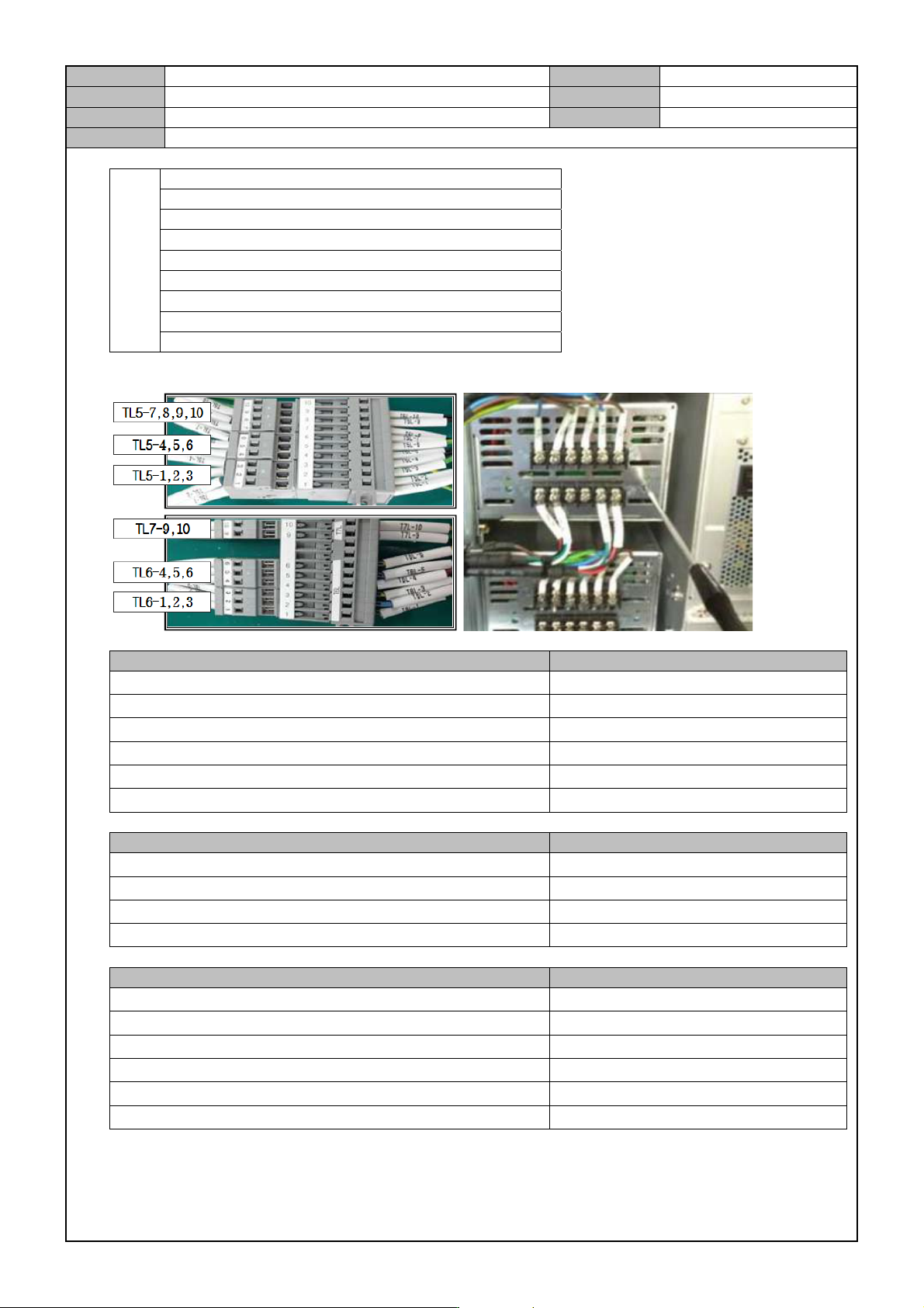
9. Using a tool, connect the cable to the Power Supply and then perform a Power Test.
Item Criteria
#1 DC POWER SUPPLY : PS1+24V, PS1-24G
DC 24.30±0.05V
#2 DC POWER SUPPLY : PS1+24V, PS1-24G
DC 24.30±0.05V
#3 DC POWER SUPPLY : PS1+24V, PS1-24G DC 24.30±0.05V
#4 DC POWER SUPPLY : PS1+24V, PS1-24G DC 24.30±0.05V
#5 DC POWER SUPPLY : PS1+24V, PS1-24G DC 24.30±0.05V
#6 DC POWER SUPPLY : PS1+24V, PS1-24G DC 24.30±0.05V
Item Criteria
SM511_PW123 CABLE : FZ12-CN5-1, FZ12-CN5-2 DC 24V ±0.72
SM511_PW123 CABLE : FZ910-CN5-1, FZ78-CN5-2 DC 24V ±0.72
SM511_PW124 CABLE : RZ12-CN5-1, RZ12-CN5-2 DC 24V ±0.72
SM511_PW124 CABLE : RZ910-CN5-1, RZ910-CN5-2 DC 24V ±0.72
Item Criteria
SM511_PW127 CABLE : T6L-7, T6L-8 DC 24V ±0.72
SM511_PW127 CABLE : T6L-9, T6L-10 DC 24V ±0.72
SM511_PW120 CABLE : T7L-1, T7L-2 DC 24V ±0.72
SM511_PW121 CABLE : T7L-3, T7L-4 DC 24V ±0.72
SM511_PW103 CABLE : T7L-6, T7L-5 DC 24V ±0.72
SM511_PW103 CABLE : T7L-8, T7L-7 DC 24V ±0.72
Model
DECAN Series
Company
SAMSUNG TECHWIN
Module
3.15 PC RACK
Version
01
Title
PC RACK CHECK
Page
3-15-9
Note
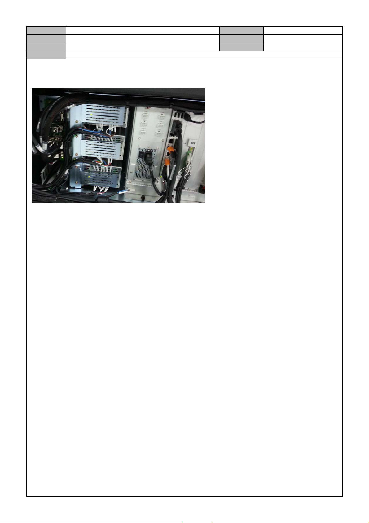
[PC RACK CHECK]
1. In the PC Rack, check the connector connection.
2. Check if the HDD Cooling Fan Operation Lamp is lit properly.
3. Check if the Power Supply has a high voltage warning sticker attached to it.
4. Check if the 24V P/S terminal board has an acryl cover attached to it.
5. From the left of the PC Rack, the order of assembly goes like the following: SBC Board, IT Master Board,
PCI Board, NT-A8 Board.
6. Check if the exterior is damaged.
Model
DECAN Series
Company
SAMSUNG TECHWIN
Module
3.15 PC RACK
Version
01
Title
POWER SUPPLY REPLACEMENT
Page
3-15-10
Note
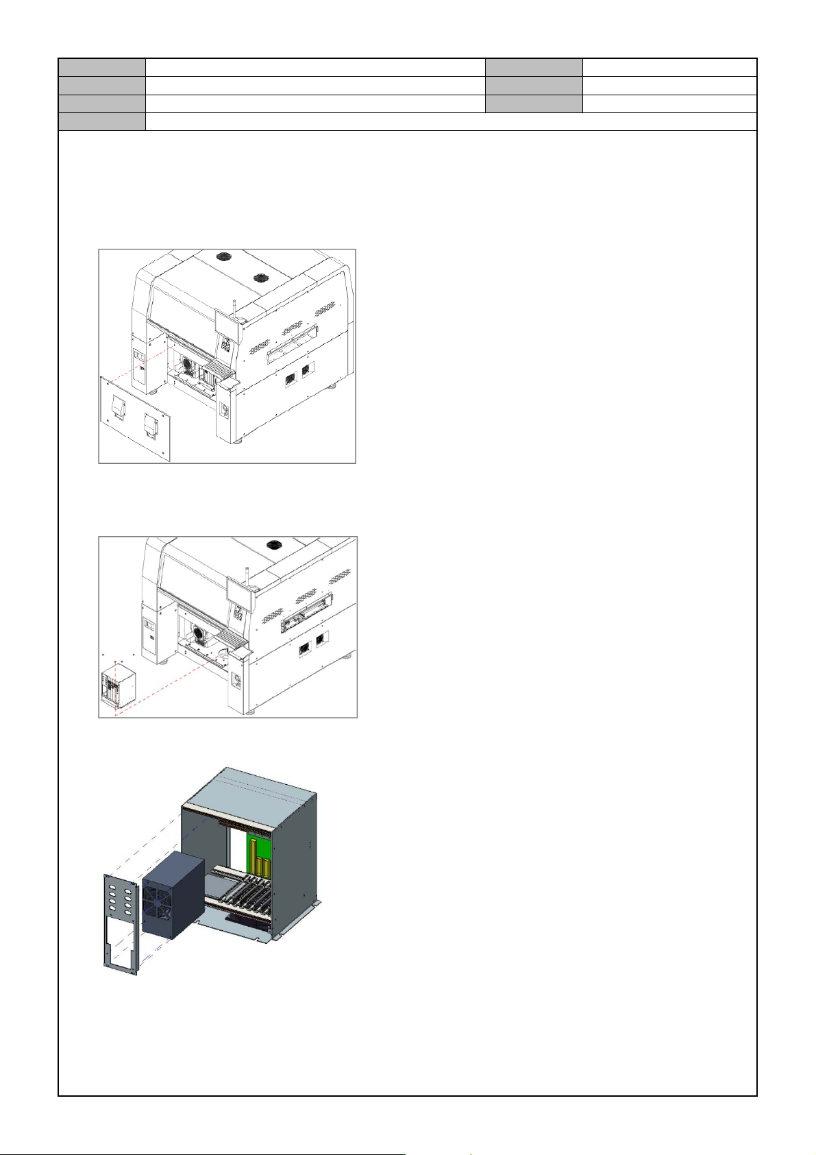
[POWER SUPPLY REPLACEMENT]
1. Turn off the PC and turn off the Main Switch in the front of the equipment.
2. Separate the front cover from the equipment.
3. Separate the cable from the PC Rack.
4. Release the fixing bolts for the PC Rack and separate the PC Rack.
5. Separate the Front Panel of the PC Rack and release the fixing bolts for the Power Supply to separate it.
6. Replace with a new Power Supply.