LBO 27 Zoll.pdf - 第65页
LBO 27" 2 Assembly instructions LBO 27" SIPLACE X4 09/2007 Edition 65 2.6.2 Inst allation of the stopper in P A1 and P A2 The two stoppers are deliver ed pre-assembled and read y wired. The stoppers have to be …
2 Assembly instructions LBO 27" SIPLACE X4 LBO 27"
09/2007 Edition
64
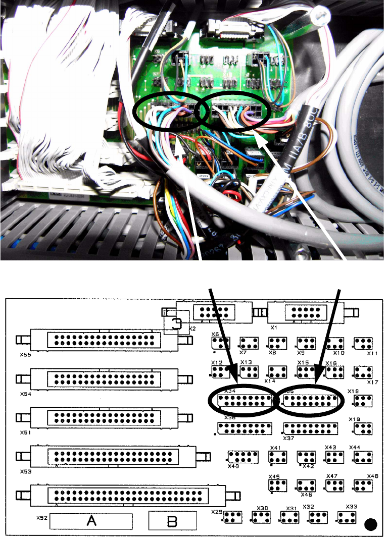
: Connect the two connection cables from PA1 and PA2 to the conversion board. The cable from
PA2 has to be connected to X35 and the cable from PA1 to X34. See following pictures for de-
tails.
2
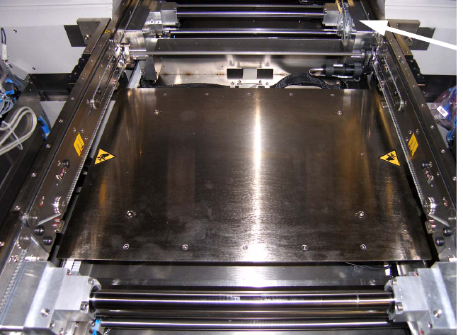
: After connecting all hoses and cables like described, close all cable ducts and covers. Put the
lifting tables back in both processing areas and mount them with the belonging screws.
Cable from PA2 to X35
Cable from PA1 to X34
LBO 27" 2 Assembly instructions LBO 27" SIPLACE X4
09/2007 Edition
65
2.6.2 Installation of the stopper in PA1 and PA2
The two stoppers are delivered pre-assembled and ready wired. The stoppers have to be moun-
ted to their positions and have to be connected to the before run cables and hoses. 2
2.6.2.1 Stopper PA1
The stopper for PA1 has to be mounted to the alloy block of the guide shaft on the right conveyor
side wall in PA1. 2
2
2
2
2
2
2
2
2
2
2
2
2
2
Alloy block for
stopper mounting
2 Assembly instructions LBO 27" SIPLACE X4 LBO 27"
09/2007 Edition
66
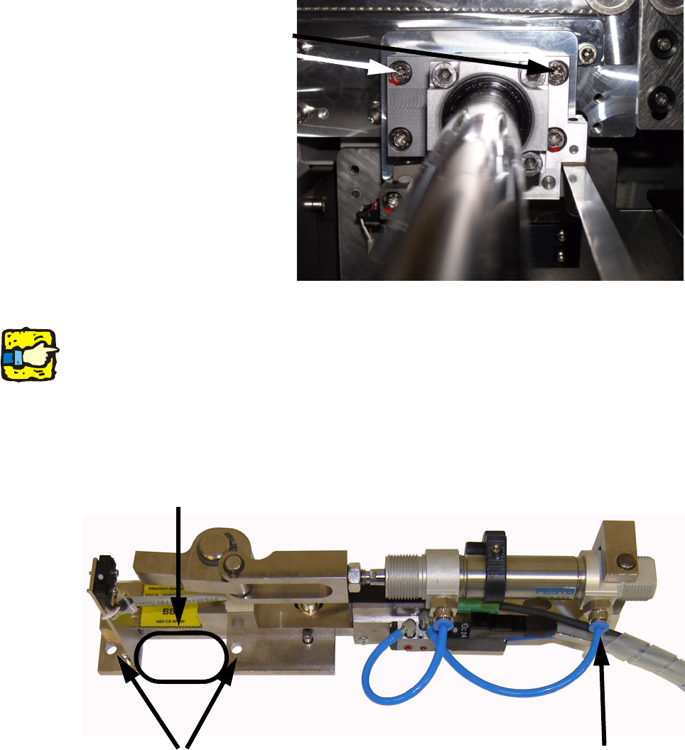
: Remove the two marked hexagon socket screws from the alloy block.
2
2
2
Keep the removed screws. You need them if the stopper will be dismounted again to fasten the
alloy block again! 2
2
: Take the stopper for PA1 and put it with the cutout onto the alloy block. Disconnect the right
hose from the pneumatic cylinder before you start.
2
2
2
Remove the 2 hexagon
socket screws M6
Cutout for alloy block
Holes fort he two M6 x 40 mm
hexagon socket screws
Disconnect hose
for mounting