LBO 27 Zoll.pdf - 第68页
2 Assembly instructions LBO 27" SIPLACE X4 LBO 27" 09/2007 Edition 68 : Reconnect the pneumatic hose to th e pneumatic cylinder . Be aware, that the hose does not rub on any other p arts of the ma chine. If ne …
LBO 27" 2 Assembly instructions LBO 27" SIPLACE X4
09/2007 Edition
67
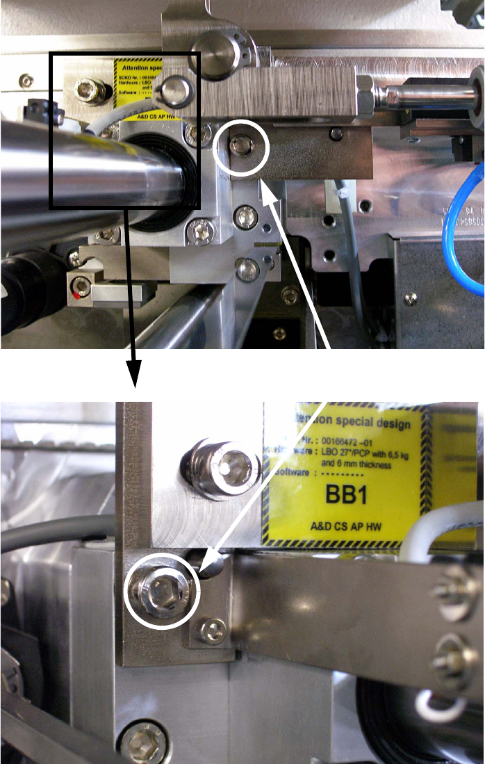
: Fasten the stopper to the alloy block by using 2 of the M6 x 40 mm hexagon socket screws.
If necessary use a long hexagon socket spanner to fasten the screws.
2
2
2
Fasten stopper with 2 M6 x 40 mm hexagon socket screws
2 Assembly instructions LBO 27" SIPLACE X4 LBO 27"
09/2007 Edition
68
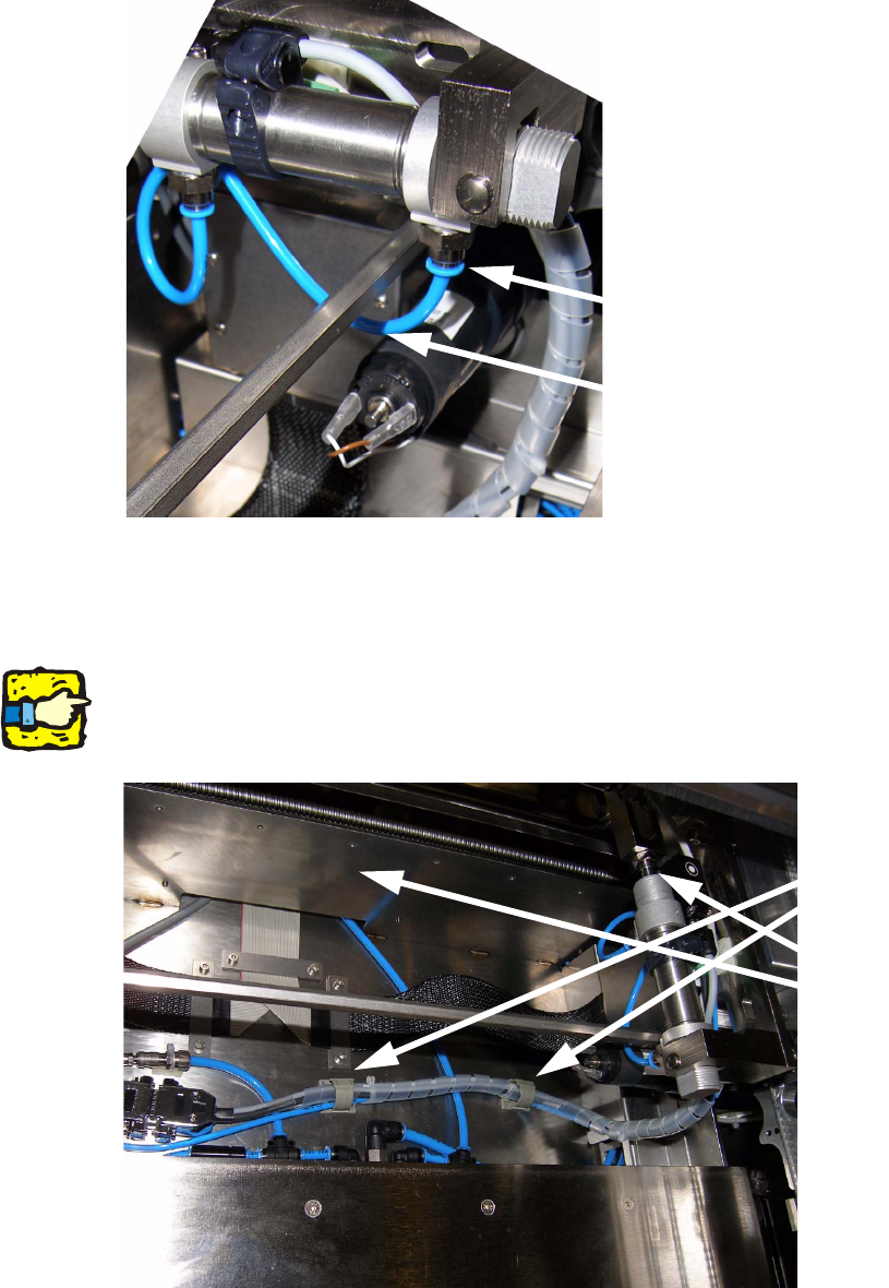
: Reconnect the pneumatic hose to the pneumatic cylinder. Be aware, that the hose does not
rub on any other parts of the machine. If necessary cut the hose into the fitting length.
2
The cable loom of the stopper has to be run like shown below: 2
: Connect the Sub-D-plug and the Sub-D-coupling and connect the PUN 4 hose with the short
PUN 6 hose.
2
The cable loom must not rub on the lifting table when lifting up and down! 2
2
2
Reconnect hose
Be aware of rubbing
parts to the hose.
Fix cable loom with two
returnable cable clips.
The cable loom must
not rub on any part of
the lifting table or
others.!
LBO 27" 2 Assembly instructions LBO 27" SIPLACE X4
09/2007 Edition
69
2.6.2.2 Stopper PA2
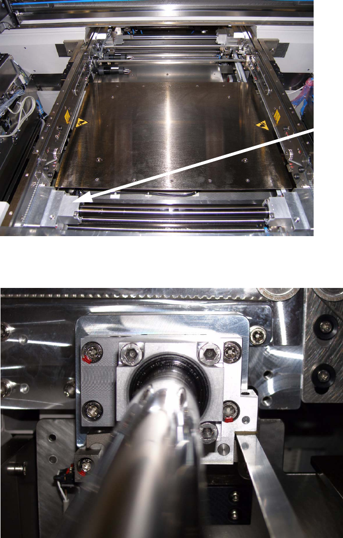
The following picture shows the processing area 2 from the output side of the machine. 2
: The stopper for PA2 has to be mounted to the alloy block of the guide shaft on the right con-
veyor side wall in PA2.
2
: Remove the two marked M6 hexagon socket screws from the alloy block.
2
Alloy block for PA2
stopper installation
2 x M6 hexa-
gon socket
screws