LBO 27 Zoll.pdf - 第70页
2 Assembly instructions LBO 27" SIPLACE X4 LBO 27" 09/2007 Edition 70 2 Keep the removed screws. Y ou need them if t he stopper will be dismounte d again to fasten the alloy block again! 2 2 : T urn the cable o…
LBO 27" 2 Assembly instructions LBO 27" SIPLACE X4
09/2007 Edition
69
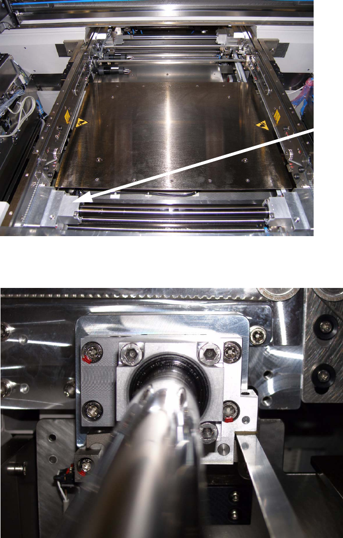
2.6.2.2 Stopper PA2
The following picture shows the processing area 2 from the output side of the machine. 2
: The stopper for PA2 has to be mounted to the alloy block of the guide shaft on the right con-
veyor side wall in PA2.
2
: Remove the two marked M6 hexagon socket screws from the alloy block.
2
Alloy block for PA2
stopper installation
2 x M6 hexa-
gon socket
screws
2 Assembly instructions LBO 27" SIPLACE X4 LBO 27"
09/2007 Edition
70
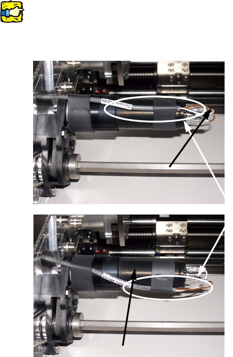
2
Keep the removed screws. You need them if the stopper will be dismounted again to fasten the
alloy block again! 2
2
: Turn the cable on the conveyor width motor like shown on the pictures below. This is to prevent
contact with the stopper.
2
2
Turn cable
LBO 27" 2 Assembly instructions LBO 27" SIPLACE X4
09/2007 Edition
71
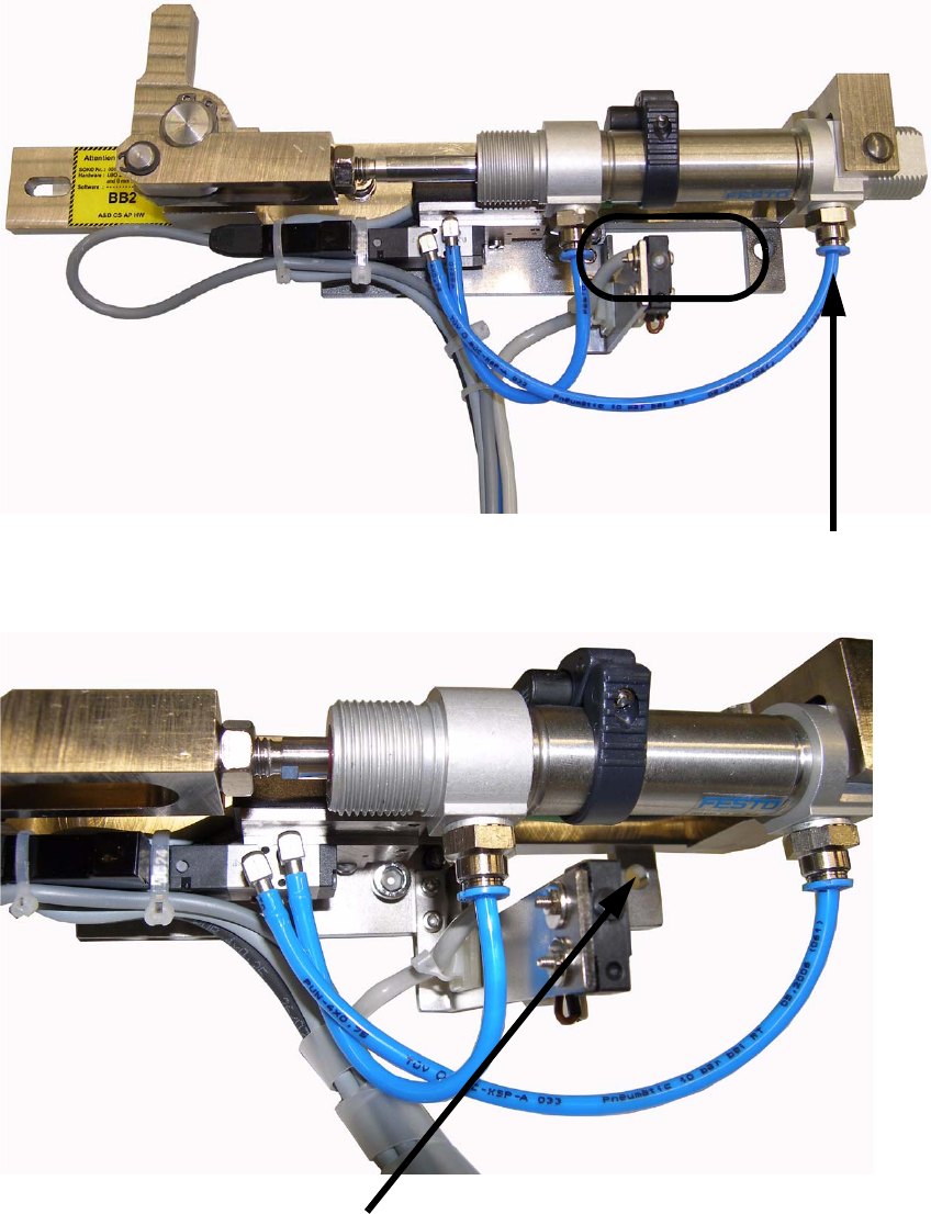
: Take the stopper for PA2 and put it with the cutout onto the alloy block. Disconnect the right
hose from the pneumatic cylinder before you start.
2
2
Cutout for the alloy block
Disconnect hose for assembly
Holes for the two M6 x 40 mm hexagon socket screws. In the left one there is already one of the
screws inserted because it’s difficult to get it in when the stopper is assembled..