LBO 27 Zoll.pdf - 第76页
2 Assembly instructions LBO 27" SIPLACE X4 LBO 27" 09/2007 Edition 76 2.7 Settings : Before you can st art the settings, make sure that no tools or materia ls are left inside the ma- chine. HEADCRASH! : If you …
LBO 27" 2 Assembly instructions LBO 27" SIPLACE X4
09/2007 Edition
75
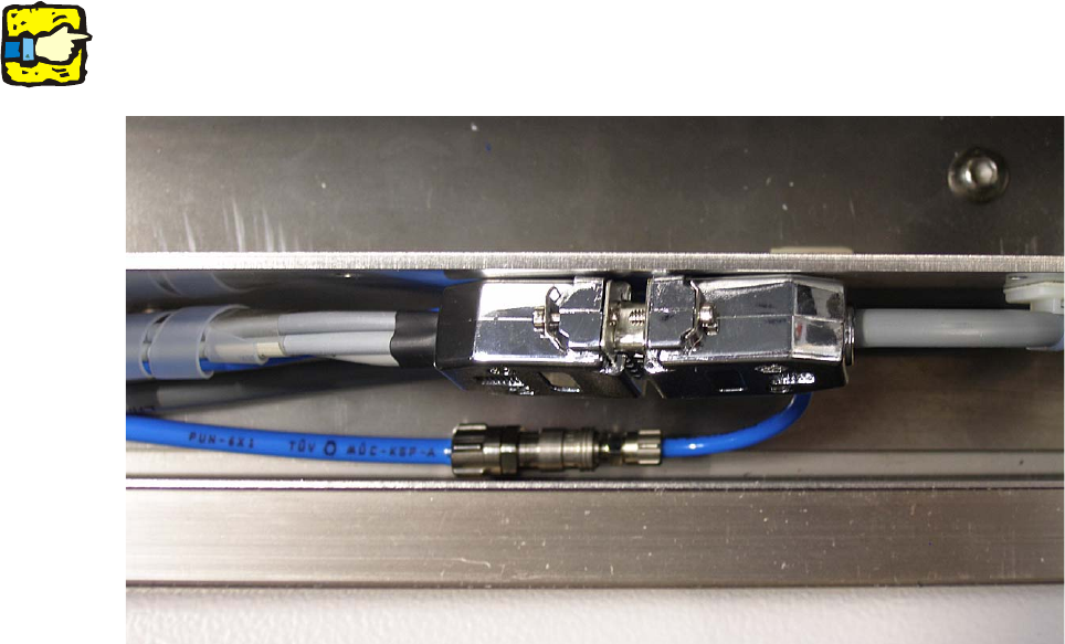
: Connect the Sub-D-plug and the Sub-D-coupling and connect the PUN 4 hose to the PUN 6
hose. See picture below.
2
All cables and hoses have to be hidden in the duct and should not reach out of it. 2
2
2
2
2 Assembly instructions LBO 27" SIPLACE X4 LBO 27"
09/2007 Edition
76
2.7 Settings
: Before you can start the settings, make sure that no tools or materials are left inside the ma-
chine. HEADCRASH!
: If you are sure that nothing is left inside the machine, turn on the machine and change to SI-
TEST after the boot up.
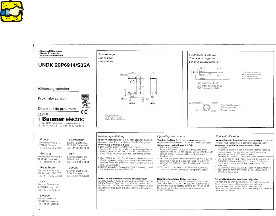
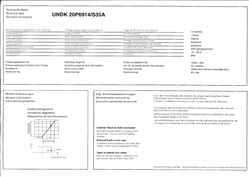
2.7.1 Calibration of the proximity switch
For calibrating the proximity sensor of the stopper, you need any test board. 2
: Adjust the conveyor to the width of this arbitrary board.
: Put in the test board and move it over the sensor of the stopper.
: Follow the instruction of the manufacturer of the sensor to calibrate it.
2
The sensor has a “teach-in locking”, which activates 5 minutes after every power-up, respectively
after the end of the last teach-in process. To deactivate the locking, the sensor has to be power-
less for a few seconds. Therefore disconnect the Sub-D-connectors for a few seconds and then
reconnect them again. Then the sensor can be calibrated for the next 5 minutes. 2
2
LBO 27" 2 Assembly instructions LBO 27" SIPLACE X4
09/2007 Edition
77
2
2
Checking the correct adjustment of the sensor 2
: Remove the PCB from the conveyor and place it sideways across the conveyor side walls
above the sensor.
The LED must not light up; the LED must only light up if there is a PCB on the conveyor.
2