LBO 27 Zoll.pdf - 第83页
LBO 27" 2 Assembly instructions LBO 27" SIPLACE X4 09/2007 Edition 83 2 : Loosen the tw o M6 hexagon socket screws on th e stopper unit. Only loosen them slightly , that you can move it forwards and backwards t…
2 Assembly instructions LBO 27" SIPLACE X4 LBO 27"
09/2007 Edition
82
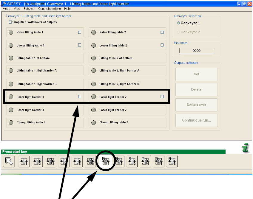
: Activate the laser light barrier 1 for the stopper adjustment in PA1 or the laser light barrier 2 for
the stopper adjustment in PA2. Set the tick behind the concerning laser light barrier and click
on “Set” to switch it on. To switch the laser off, click on “Delete”.
2
2
2
2
2
2
2
2
2
2
2
2

LBO 27" 2 Assembly instructions LBO 27" SIPLACE X4
09/2007 Edition
83
2
: Loosen the two M6 hexagon socket screws on the stopper unit. Only loosen them slightly, that
you can move it forwards and backwards to adjust the stopper position.
2
Set the tick behind the con-
cerning laser light barrier
Click to „Set“ to switch
on the chosen laser
Click to „Delete“ to switch
off the chosen laser
Move stopper for adjustment!
Loosen the two screws
to move the stopper
2 Assembly instructions LBO 27" SIPLACE X4 LBO 27"
09/2007 Edition
84
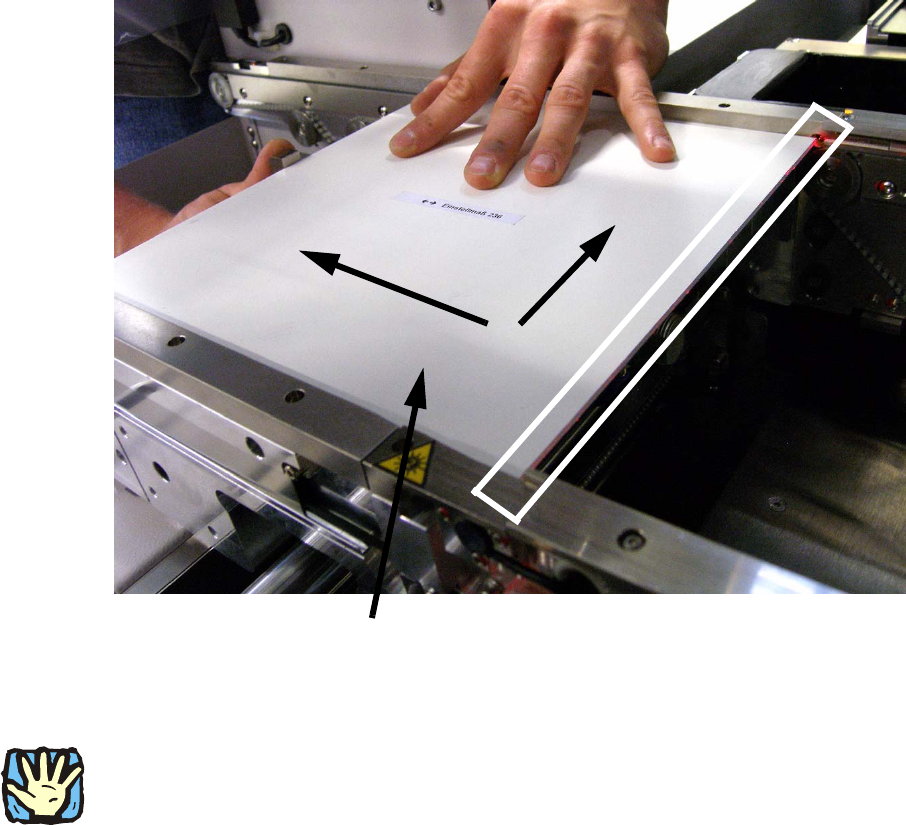
: With activated laser, the calibration board has to be pushed to the stopper. Push the board onto
the stopper and the fixed edge of the machine and move the stopper into the correct position.
In the correct position, the laser is visible on the whole edge of the calibration board. See pic-
ture below.
: If the stopper is at the correct position, remove the board carefully and fasten the two before
loosen screws. Then check the stopper position again by using the calibration board. Use
threadlocker to prevent a loosening of the screws.
2
2
2
CAUTION:
Deactivate the laser light barriers immediately after the successful adjustment of the stoppers and
deactivate the “safety mode (low speed)” in the run options. 2
2
2
Push the calibration board in this two directions