LBO 27 Zoll.pdf - 第86页
2 Assembly instructions LBO 27" SIPLACE X4 LBO 27" 09/2007 Edition 86 : S tart the program “lp- transport.ht” on the de livered CD by double click. 2 Hauptmenue T ransport Siplace HF 2 T race-Meldungen au s: &a…
LBO 27" 2 Assembly instructions LBO 27" SIPLACE X4
09/2007 Edition
85
2.7.3 Settings in the conveyor firmware via Hyperterminal – adjustment of the run-
time delay in the conveyor control
For changing the settings of the conveyor firmware via Hyperterminal, it is necessary to connect
the conveyor control unit to an external computer.
Use a seriell connection cable (1:1) and follow the instructions: 2
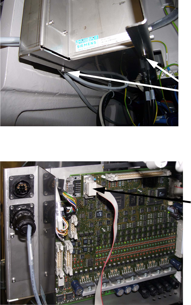
: The transport control is located over the main pneumatic unit of the machine.
Remove the two marked screws to pull out the control unit.
2
: Connect the transport control unit with the external computer by using the seriell connection
cable.
2
2 screws
Serial connection cable
2 Assembly instructions LBO 27" SIPLACE X4 LBO 27"
09/2007 Edition
86
: Start the program “lp-transport.ht” on the delivered CD by double click.
2
Hauptmenue Transport Siplace HF 2
Trace-Meldungen aus: 'Strg'+'A', ein: 'Strg'+'E' 2
1 - Bug-Report 2
2 - Transport Info 2
3 - Einstellen Meldungen 2
4 - Steuerplatine 2
5 - Einzelkomponenten 2
6 - Dauerlauf 2
7 - Firmware-Test 2
8 - Koppeln Barcode-Schnittstelle 2
9 – parameter 2
2
{Choose 9} 2
2
parameter track 1 (and common parameter) 2
1 - list parameter 2
2 - modify parameter 2
3 - save to EEPROM 2
t - change track 2
0 – quit 2
2
{Choose 1} 2
2
parameter track 1 2
1, 6, // version 2
10, 500, // [mm/s] maximum velocity conveyor 2
11, 350, // [mm/s] velocity drive-in machine 2
12, 350, // [mm/s] velocity drive-out machine 2
13, 50, // [0.1m/s²] maximum acceleration 2
14, 60, // [mm/s] velocity laser-light barrier 2
15, 25, // [0.1m/s²] deceler.laser-light barrier 2
16, 350, // [mm/s] velocity sensor laser-light 2
20, 0, // barcode scanner 2
21, 0, // ceramic centering unit 2
22, 0, // optional stopper 2
LBO 27" 2 Assembly instructions LBO 27" SIPLACE X4
09/2007 Edition
87
23, 0, // type vacuum tooling = AVSP 2
24, 0, // no verification of clamping with motor 2
41, 0, // left side fixed, width adjustment 2
43, 0, // fixed rails pitch (actual) 2
44, 0, // fixed rails pitch (target) 2
48, 65, // [%] force stepping motor width adj. 2
49, -993, // [um] offset width adjustment 2
50, -3813, // [um] offset fixed rail 2
47, 1, // position fixed rail ok 2
60, 991, // [um] calibration position 1, width adj. 2
61, 21513, // [um] calibration position 2, width adj. 2
62, 326, // [um] cavity driver, input, width adj. 2
63, -447, // corr. a0, sensor width adj., input 2
64, -952, // corr. a1, sensor width adj., input 2
65, 118, // corr. a2, sensor width adj., input 2
66, 384, // [um] cavity driver, output, width adj. 2
67, -369, // corr. a0, sensor width adj., output 2
68, -598, // corr. a1, sensor width adj., output 2
69, 121, // corr. a2, sensor width adj., output 2
70, 365, // [um] cavity driver, middle, width adj. 2
71, -150, // corr. a0, sensor width adj., middle 2
72, -1952, // corr. a1, sensor width adj., middle 2
73, 397, // corr. a2, sensor width adj., middle 2
80, 60, // [mm/s] velocity stopper 2
81, 350, // [mm/s] velocity sensor stopper 2
82, 25, // [0.1m/s²] deceleration stopper 2
83, 600, // [ms] drive-up time stopper 2
84, 60, // [mm/s] velocity stopper LBO 2
85, 300, // [mm/s] velocity sensor LBO 2
86, 25, // [0.1m/s²] deceleration stopper LBO 2
87, 600, // [ms] drive-up time stopper LBO 2
88, 10, // [%] velocity split for combined PCB 2
89, 200, // [ms] drive-up time stopper comb. PCB 2
90, 10, // [mm] bumper height LT (=0->40mm clearance) 2
2
2
2
2
2