00196715-01_IM_SSW_704_DE_EN.pdf - 第19页
Installation Manual, Station Software Version 704.01 04/2010 Edition 19 of 60 Old subsystem name (<70x) New subsystem name (70x) Name --- CCPAPR 1) Pressure regulation valve, CPP head --- CPPAVA 1) Valve cluster, CPP …

Installation Manual, Station Software Version 704.01 04/2010 Edition
18 of 60
4.1.3.2 Comparison of old and new names of the subsystems
Old subsystem name (<70x) New subsystem name (70x) Name
A AXIALL General axes (including free axis), excluding
DP axes of the C&P20A head
B COMTAB Component table
C VHSAXS Star axis of C&P20A head
E IOMODU CAN I/O module
F (Replaced by AXIALL) Free axis
G TAPCUT Tape cutter
H VHSHED C&P20A head
I TWIHED Twin Head
J VHSAXD DP axis of C&P20A head
L TWIAPR / VHSAPR Pressure regulation valve
(Twin Head / C&P20 head)
M MTCHNG MTC
N ---
O ---
P TWIAXZ Z-axis, Twin Head
Q ---
R TWIAXD DP axis, Twin Head
T CONVEY PCB conveyor
U FEEDER Feeder
V ILLUMI Vision
W VHSAXZ Z-axis, C&P20A head
X GANAXX X-axis
Y GANAXY Y-axis

Installation Manual, Station Software Version 704.01 04/2010 Edition
19 of 60
Old subsystem name (<70x) New subsystem name (70x) Name
--- CCPAPR
1)
Pressure regulation valve, CPP head
--- CPPAVA
1)
Valve cluster, CPP head
--- CPPAXD
1)
DP axis, CPP head
--- CPPHED
1)
CPP head
--- CPPSCO
1)
Component sensor
--- CPPSZD
1)
Z-bottom, CPP head
--- WPCAXI
2)
WPC5 feed axis and lift axis
--- WPCHNG
2)
WPC5 / WPC6
1)
as of 702.xx
2)
as of 703.xx
Installation Manual, Station Software Version 704.01 04/2010 Edition
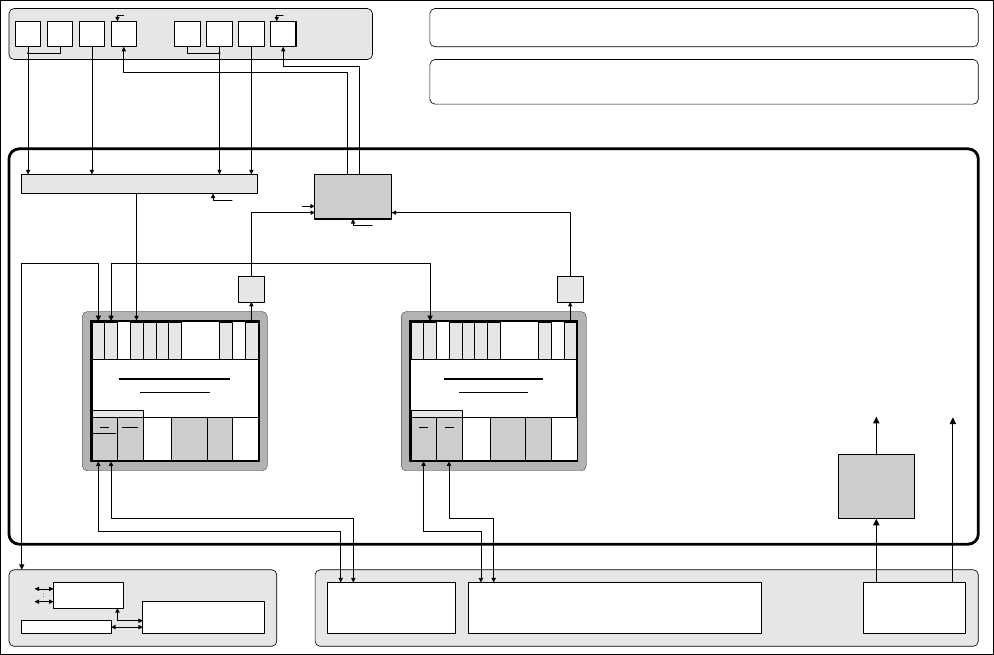
4.2 SIPLACE X- and SX-series hardware components
The following two diagrams show the hardware components of the computer system for the SIPLACE X2,
X3, X4 and X4I machines in two-computer operation:
Camera system
for 2 placement areas with 4 placement heads
with component Vision and board position recognition
PS
Power supply
Production line
LAN (hub)
Customer LAN
1 2
CAN bus
Remote control
Machine
Structure of the computer unit and its interfaces
SIPLACE X2, X3, X4, X4I
Basic set-up with 2 x Box PC 627 Serie / SW: 704 / 2-computer operation
Programming system
SIPLACE Pro
Programming system
and external networks
LAN
Computer unit
Video multiplexer
with splitter
VGA VGA
VGA VGA
to Box PCs 627
+5 V
Output
DC/DC
converter
Input
Touch
screen 1
User
interface
Touch
screen 2
Keyboard
1
Keyboard
2
Mouse
1
Mouse
2
Monitor
1
Monitor
2
USB hub
+5 V
+24 V+24 V
to
video multiplexer
and
USB hub
+24 V
+48 V +5 V
Adapter
DVI-I
to VGA
Pentium M 760 2 GHz, HSP 1 GB
Vision computer
SIMATIC Box PC 627
P C I - B u s
Hot-
link
PCI
Hot-
link
PCI
C
O
M
1
D
V
I
-I
U
S
B
1
U
S
B
2
U
S
B
3
HD
40 GB
L
A
N
1
U
S
B
4
L
A
N
2
Connection:
compact
flash drive
Adapter
DVI-I
to VGA
Pentium M 760 2 GHz, HSP 1 GB
Machine computer
SIMATIC Box PC 627
P C I - B u s
C
O
M
1
D
V
I
-I
U
S
B
1
U
S
B
2
U
S
B
3
HD
40 GB
L
A
N
1
U
S
B
4
L
A
N
2
Connection:
compact
flash drive
CAN
1 2
PCI
COM 168
PCI-...
Fig. 4-1: Hardware components of the computer system for the SIPLACE X-series in two-computer operation (block diagram)
20 of 60