YSH20_mpl_je.pdf - 第4页
Contents 1. Base Section 2. Cover Section 3. Feeder Holder Section 1-1. Sub Assy 2-1. Acril Door / Conveyor 2-2. Base Cover 3-1. Feeder Holder A10 (B10) 3-2. Reel Holder A-T ABLE B-T ABLE 4 .Head Section 5. Nozzle Sectio…
Note
Rank A : The functions of these parts gradually deteriorate with operating time.
Rank B : The machine stops immediately if the functions of these parts are disabled.
Rank C : The machine still operates even if the functions of these parts are disabled,
because there are many parts.
Rank E : The functions of consumable part gradually deteriorate with operating time.
/ : Maintenance is excluded (The screws are also equal, display is omitted)
Level
: Aims to undergo basic maintenance training and have the capability to do the
job.
Level
r
: Yamaha Corp. aims to render exclusive training
Level
Í
: Yamaha Corp. Service Engineering
Rev.
: It had a change without the compatibility. Please be careful at the time of the
parts ordering.
Level column
Make use of these as reference, “
•
r
•×”, as mentioned in the Level column.
“
” It is based on taking the basic maintenance training, and being able to do
equal work.
“
” Please contact our company service when it is judged that the customer’s
condition difcult.
From the problem that arises from these, we cannot assume responsibility such as
accidents.
NOTE
RankA: 機能が徐々に失われる可能性のある部品。
RankB: 機能を失うとマシンの即停止に繋がる部品。
RankC: 機能を失っても複数あるのでマシンの即停止とはならない部品。
RankE: 機能が徐々に失われていく消耗部品。
/ :メンテナンス対象外(ネジ類も同等、但し表示省略)
Level
: 基礎メンテナンストレーニングを受けた方、又は同等の作業ができる方が対象。
Level
r
: ヤマハの専用トレーニングを受けた方が対象です。
Level
Í
: ヤマハのサービスマンが対象です。
Rev.
:過去に互換性の無い変更が入った部品。部品発注時は注意してください。
Level 欄について
Level 欄に記載されている
“
•
r
•×”
はご参考としてご活用ください。
“
”
は基礎メンテナンストレーニングを受けた方、又は同等の作業ができる方を
基準にしております。
“
”
であってもお客様が難しいとご判断された時は弊社サービスまでご連絡ください。
これらに起因する不具合、事故等についての責任は負いかねます。
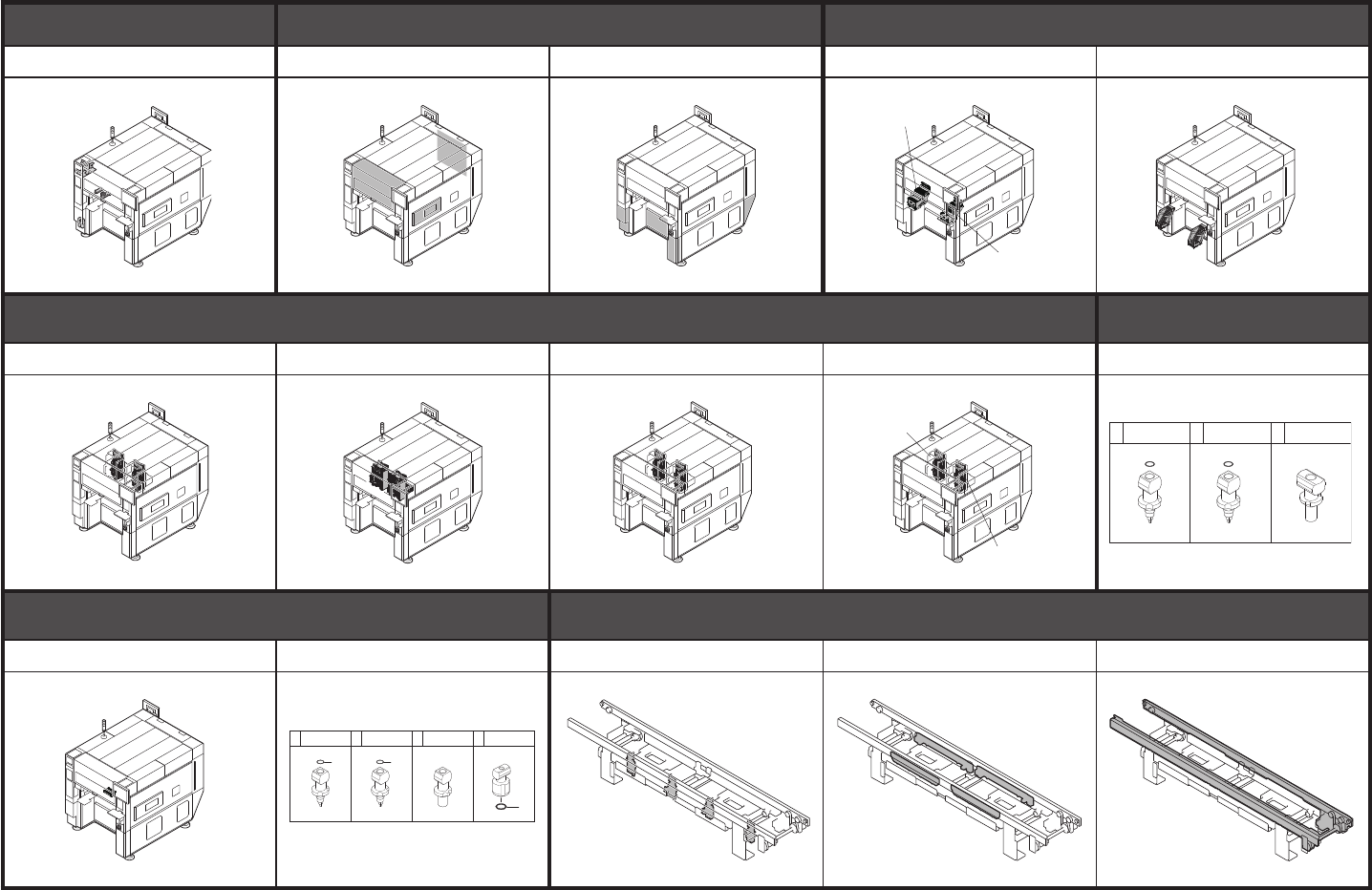
Contents
1. Base Section 2. Cover Section 3. Feeder Holder Section
1-1. Sub Assy 2-1. Acril Door / Conveyor 2-2. Base Cover 3-1.
Feeder Holder A10 (B10)
3-2. Reel Holder
A-TABLE
B-TABLE
4 .Head Section 5. Nozzle Section
4-1. FF Nozzle Holder 4-2. FF Cover / Brkt / Valve 4-3. 4M Nozzle Holder 4-4. 4M Valve/Bracket 5-1
. FF Head Nozzle Selection
5. Nozzle Section 6. Conveyor Unit Section
5-2
. FF Nozzle Changer (OP.)
5-3. 4M Head Nozzle Selection
6-1. Stopper 6-2. Clamp Board 6-3. Board Transfer
431 NOZZLE 61A/401A NOZZLE 62A/402A NOZZLE 403A
A-HEAD
B-HEAD
2
NOZZLE 61A ASSY 31 54 NOZZLE 63A
6
2
NOZZLE 64B ASSYNOZZLE 62A ASSY
1 / 3

6. Conveyor Unit Section
7 . Force Control Unit Section
8. FDR Section
6-4. PCB Sensor Set (KEY) 7-1. Force Control Unit 8-1. Set Up ST on MC 8-2. FDR Power ST 8-3. FDR Stand Type144
9.
Controller Section
10. Exterior, etc Section 11 .Wafer LZ-axis Section
9-1. Control Box 10-1. Exterior, etc.
10-2. Key Board & Mouse /
LCD Stay Assy
11-1. Carrige Assy 11-2. Foot / Valve
11 .Wafer LZ-axis Section
12 .Wafer LCY-axis Section
13 .Wafer Head Section
11-3. Carrige Sensor / Exterior
11-4. Door / Guide 11-5. Stopper 12-1. LCY-axis 13-1. Nozzle Selection
Contents
2
3
4
6
8
10
12
16
19 21
23
25
1.7
12U1
D
1.7
D
2.7
D
2.7
D
2.7
D
2.7
D
1.7
D
1.7
D
1.7
D
1.7
D
1.7
D
12U1 12U1
12U1
12U1 12U1 12U1
12C 12C 12C 12C
1 5 7 9 11 13
15 17 20 22 24
NOZZLE 07 ASSY NOZZLE 10 ASSY NOZZLE 12 ASSY NOZZLE 15 ASSY NOZZLE 20 ASSY NOZZLE 38 ASSY
NOZZLE 50 ASSY NOZZLE 71 ASSY NOZZLE 86 ASSY NOZZLE 112 ASSY NOZZLE 120 ASSY
14
2
4
2
4
2
4
2
4
2
4
2
4
18
4
18
4
18
4
18
4
2 / 3