2OM-1088-002.pdf - 第169页
Tg0699-PM-D2 Output Interval : When "Interval" is selected as *2 Output Mode, set the interval time of the PCB output. Make the ten-key window appear and enter the time in the text box. 0207-001 Chapter 1 4-22 …

Tg0699-PM-D2
Auto Stop Mode: When this mode is selected, the machine auto-
matically stops running in the following case A
or B.
A. The machine stops running based on the fol-
lowing criteria.
1) There is no P.C.B. inside the machine.
2) The machine is waiting for a P.C.B. to be
transferred from the input machine and
more than 2 seconds has elapsed since
the "RUN" signal of the input machine is
turned off.
B. The machine stops running based on the
following criteria
1) There is no P.C.B. inside the machine.
2) The input machine is stopped.
Auto Line Start Mode : When this mode is selected and the out-
put machine starts the automatic opera-
tion, this machine is interlocked and also
starts its automatic operation.
This function does not work while the screen saver func-
tion is activated.
Auto Line Stop Mode : When this mode is selected and the out-
put machine stops the automatic opera-
tion, this machine is interlocked and also
stops its automatic operation.
*5 Timer Setting (sec)
It can be determined how many seconds are required for the input
and output conveyors to be activated to receive a P.C.B. from the
input machine and discharge a P.C.B. to the output machine.
Input Conveyor : Enter the operating time of the input conveyor
in the text box.
Approximately 2 seconds must be added to
the time required to receive a P.C.B. from the
input machine and the total time must be en-
tered.
Output Conveyor : Enter the operating time of the output con-
veyor in the text box.
Approximately 2 seconds must be added to
the time required to discharge a P.C.B. to the
output machine and the total time must be en-
tered.
0207-001 Chapter 1 4-21
3.1 "Transfer Mode Set-up" Tab

Tg0699-PM-D2
Output Interval : When "Interval" is selected as *2 Output
Mode, set the interval time of the PCB output.
Make the ten-key window appear and enter the time in the
text box.
0207-001 Chapter 1 4-22
3.1 "Transfer Mode Set-up" Tab
Tg0699-PM-D2
••
••
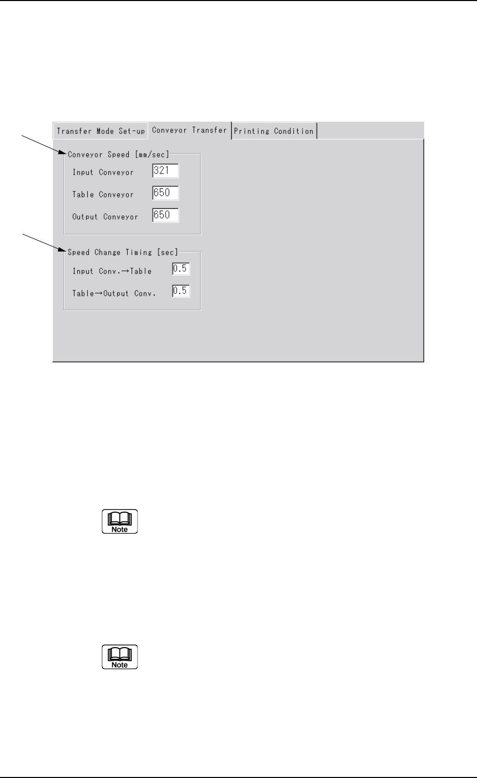
• Sheet Composition
*1 Convetor Speed [mm/ sec]
The PCB transfer speeds of the L conveyor, table conveyor and
R conveyor are set.
Display the "Ten-Key" window and input each speed.
*2 Speed Change Timing [sec]
The time period, where the transfer conveyor and table conveyor
maintain the maximum speed, is set before the speeds of the
above conveyors have been decreased to the speeds set in *1.
Display the "Ten-Key" window and input each speed.
0207-001 Chapter 1 4-23
3.2 "Conveyor Transfer" Tab
*1
*2
3.2 "Conveyor Transfer" Tab
••
••
• Sheet Layout
When the [Transfer Conveyor] tab is pressed in the "Device Data"
submenu window, the following tab sheet appears.
Fig. 3D14