2OM-1088-002.pdf - 第170页
Tg0699-PM-D2 • • • • • Sheet Composition *1 Convetor Speed [mm/ sec] The PCB transfer speeds of the L conveyor , table conveyor and R conveyor are set. Display the "T en-Key" window and input each speed. *2 Spe…

Tg0699-PM-D2
Output Interval : When "Interval" is selected as *2 Output
Mode, set the interval time of the PCB output.
Make the ten-key window appear and enter the time in the
text box.
0207-001 Chapter 1 4-22
3.1 "Transfer Mode Set-up" Tab
Tg0699-PM-D2
••
••
• Sheet Composition
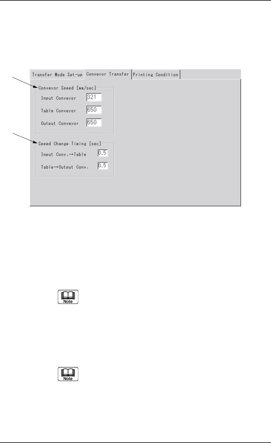
*1 Convetor Speed [mm/ sec]
The PCB transfer speeds of the L conveyor, table conveyor and
R conveyor are set.
Display the "Ten-Key" window and input each speed.
*2 Speed Change Timing [sec]
The time period, where the transfer conveyor and table conveyor
maintain the maximum speed, is set before the speeds of the
above conveyors have been decreased to the speeds set in *1.
Display the "Ten-Key" window and input each speed.
0207-001 Chapter 1 4-23
3.2 "Conveyor Transfer" Tab
*1
*2
3.2 "Conveyor Transfer" Tab
••
••
• Sheet Layout
When the [Transfer Conveyor] tab is pressed in the "Device Data"
submenu window, the following tab sheet appears.
Fig. 3D14
Tg0699-PM-D2
••
••
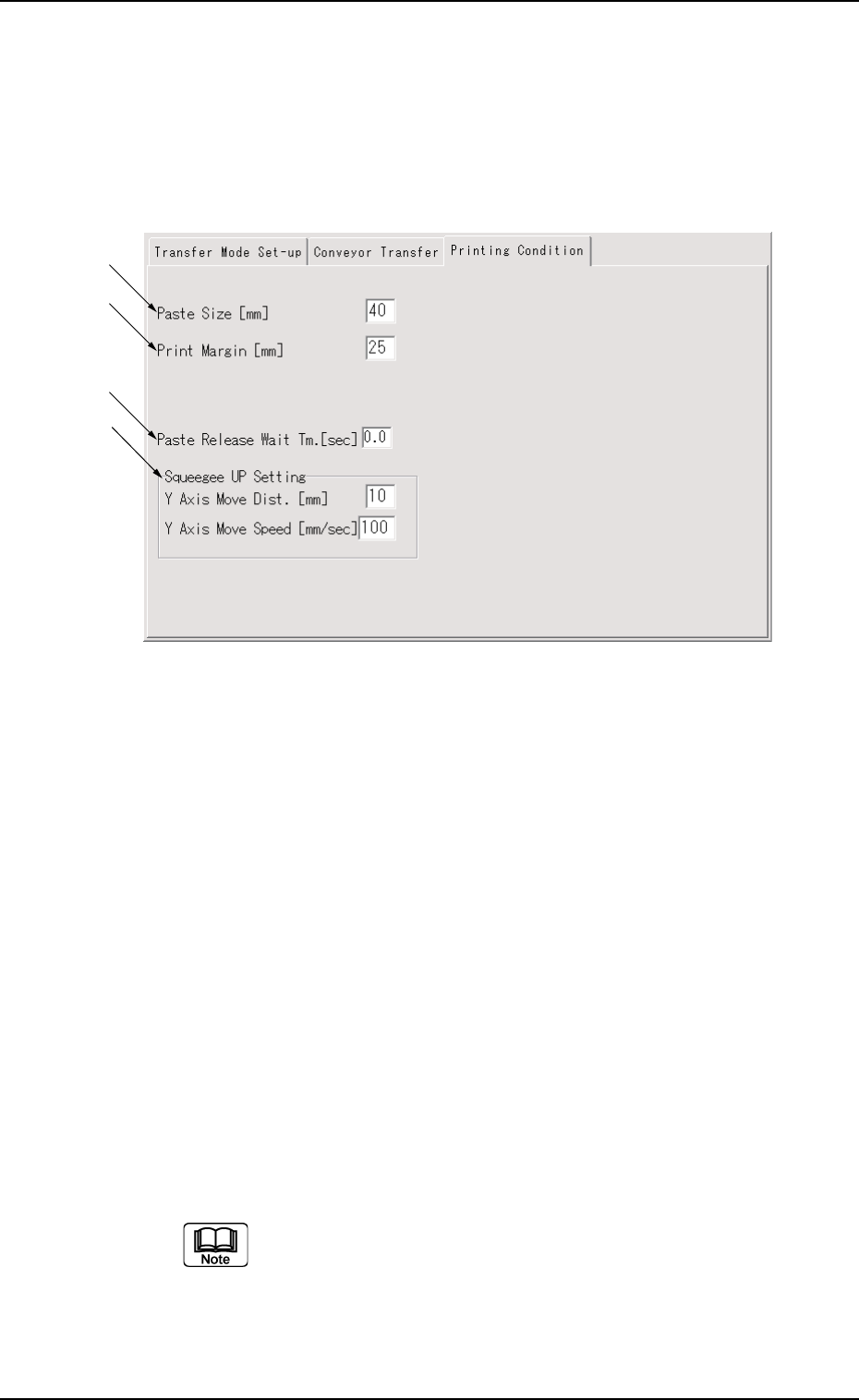
• Sheet Composition
*1 Paste Size
The width of solder paste in direction X in the printing operation
is set.
This is the data to find the squeegee offset value (So) shown in
the following figure, which is calculated by the machine using the
following formula.
Unit : mm
So = Sd × 2 - Ps
Sd : Distance between Squeegees
(Calculated from squeegee angle)
Ps : Paste Size (Initial Value : 40 mm)
Display the "Ten-Key" window and input the paste size.
0207-001 Chapter 1 4-24
3.3 "Printing Condition" Tab
3.3 "Printing Condition" Tab
••
••
• Sheet Layout
When the [Printing Condition] tab is pressed in the "Device Data"
sub-menu window, the following tab sheet appears.
Fig. 3D15
*1
*2
*3
*4