2OM-1088-002.pdf - 第460页
Tg0699-PM-D2 4.2 Electrical Circuit Diagram of Each Section 0207-001-(M782W A---0001) Chapter 3 3-44 4.2 Electrical Circuit Diagram of Each Section Integrated Block Diagram Cleaning Section Relay Air Blower Nozzle Relay …
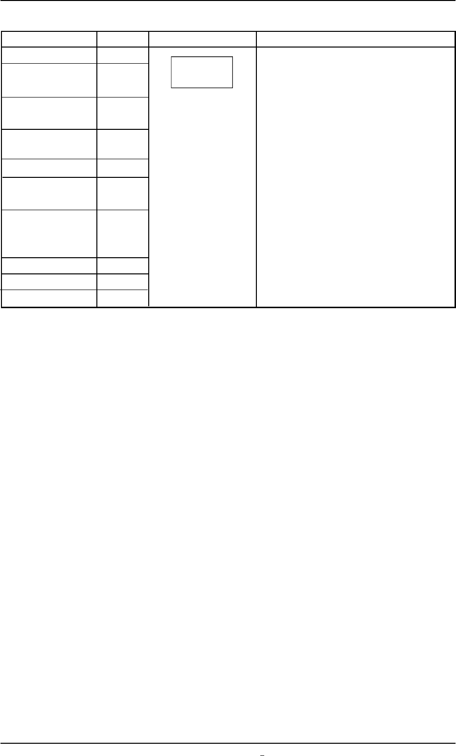
Name Symbol Graphic Symbols Remarks
Noise Filter Z* The graphic symbol generally represents
Servomotor ASMD* a unit.
Driver Different circuit symbols are used to the
Stepping APMD* classification of electrcal components.
Motor Driver
Speed Control ASCP*
Driver
Switching Power G*
Brake Power for G*
Servomotor
Lighting Surge FV*
Protector
Unit P.C.B. U*
Hard Disk Drive HDD*
Floppy Disk Drive FDD*
Other Units
0207-001 Chapter 3 3-43-2
Tg0699-PM-D2
4.1 Electrical and Electronic Symbols
Tg0699-PM-D2
4.2 Electrical Circuit Diagram of Each Section
0207-001-(M782WA---0001) Chapter 3 3-44
4.2 Electrical Circuit Diagram of Each Section
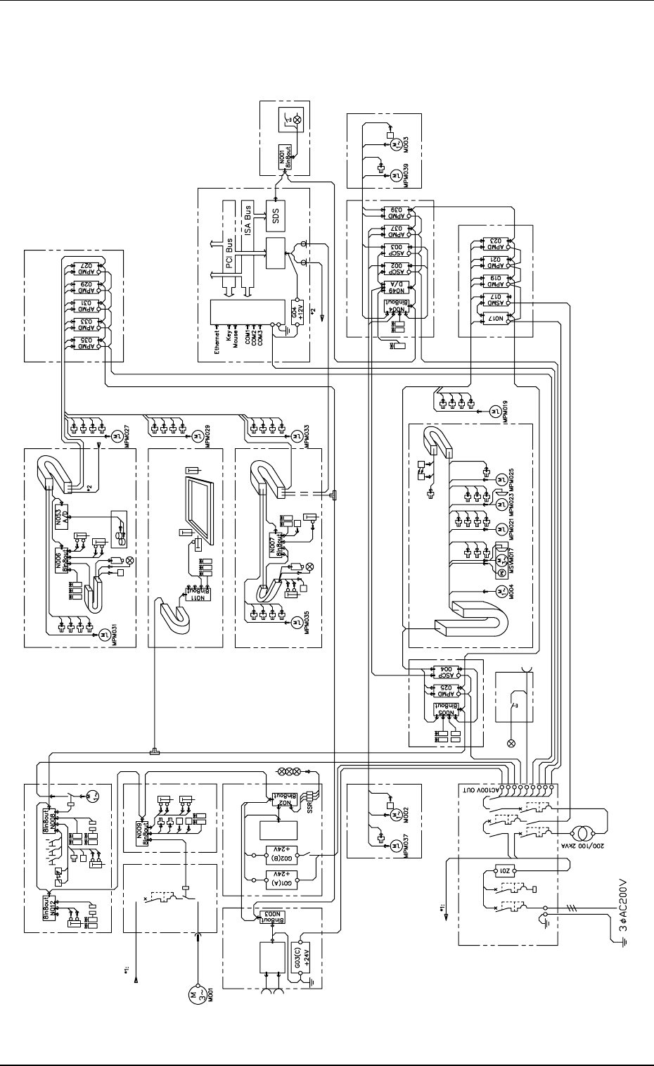
Integrated Block Diagram
Cleaning Section
Relay
Air Blower
Nozzle
Relay
Take-Up
Screen Recognition
X-Axis
Squeegee Head Section
Load Cell
Front
Up/Down
Rear
Up/Down
Driver 2 Section
Control Box
Squeegee
Driving Axis
Screen Y-Axis
Screen Brake
Screen Holer Section
P. E. C. Recognition Section
Relay Sequence Section
Chuck Cleaning
Blower Unit Section
Utility Section
Vacuum Pump
Signal from
Input Machine
Signal from
Output Machine
Front and Rear
I/F Section
I/F
Board
Relay
P. C .B .
Signal Tower
P.E.C.
Recognition X-Axis
P.E.C. Recognition
Y-Axi s
Stopper
Panel Computer
Recognition
Operation Panel
Section
R Conveyor
R_Rotation
R_Conveyor
Width
R Conveyor
L_Rotation
L_Conveyor
Width
P.C.B. Transfer Section
Driver 1 Section
Table Section
P.C.B. Chuck
Section
Main Power
Supply Section
Lighting for
Operation
Console
Section
AC Power Outlet
Conveyor
Motor
Ta bl e
Z-Axis
Ta bl e
θ-Axis
P. C . B.
Up/Down
Axis
Ta bl e
Width
Axis
Ta bl e
X-Axis
Trans
: From Main
Power Supply
: To Vacuum Pump
Lightning
Paste Check
: From Control
Box
Screen Positioning
P.C.B. Check
Overlapped Detection
Warpage Holding
P.C.B. Horizontal Clamping
Width Error Detection
: To Squeegee
Head Section
Electro-pneumatic
Regulator
Tg0699-PM-D2
SDS Block Diagram
0207-001-(M782WA---0002) Chapter 3 3-45
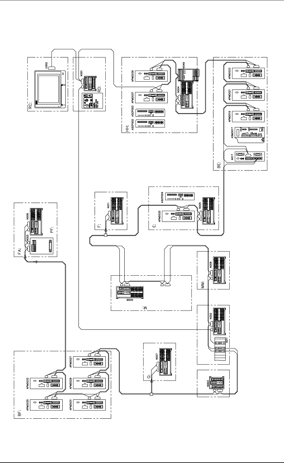
SDS Block Diagram
Driver 2 Section
P.E.C. Recognition X-Axis
P.E.C. Recognition
Y-Axis
Screen Recognition X-Axis
Screen Y-Axis
P.E.C. Recogniton Section
RJ: Front and Rear
I/F Section
RG: Relay Sequence Section
Cleaning Section
Screen Holder
Section
P.C.B. Chuck Section
Table Width Axis
Utility Section
Suqeegee Head Section
Control Box Section
Operation Panel
Section
P.C.B. Transfer Section
L Conveyor Width Axis
R Conveyor Width Axis
Driver 1 Section
Table X-Axis
Ta bl e θ-Axis
Table Y-Axis
Ta bl e
Up/Down Axis
Squeegee Driving Axis
Pro Flow
With terminal resistance
With terminal
resistance