2OM-1088-002.pdf - 第67页
Tg0699-PM-D2 1.2 Operation Data 0207-001 Chapter 1 2-8 1.2.3 PCB Backup (1) Chuck Stage Select Select the method to fix the P .C.B. on the table chute. The specified data is used to determine the P .C.B. fixing method of…
Tg0699-PM-D2
1.2 Operation Data
0207-001 Chapter 1 2-7
(11) Separate Distance
Set the distance of the screen frame to be kept when it is
separated from the P.C.B. after the end of printing.
Unit : mm
Data Input Range : 0 to 9.9
(12) Prntng. Correction (Back)
X [mm], Y [mm],
θθ
θθ
θ [ °
]
Set parameters to correct the relative position (trace quantity)
between the P.C.B. and the screen kept when the squeegees
move backward (from the front to the rear side).
(13) Prntng. Correction (For.)
X [mm], Y [mm],
θ θ
θ θ
θ [ ° ]
Set parameters to correct the relative position (trace quality)
between the P.C.B. and the screen kept when the squeegees
move forward (from the rear to the front side).
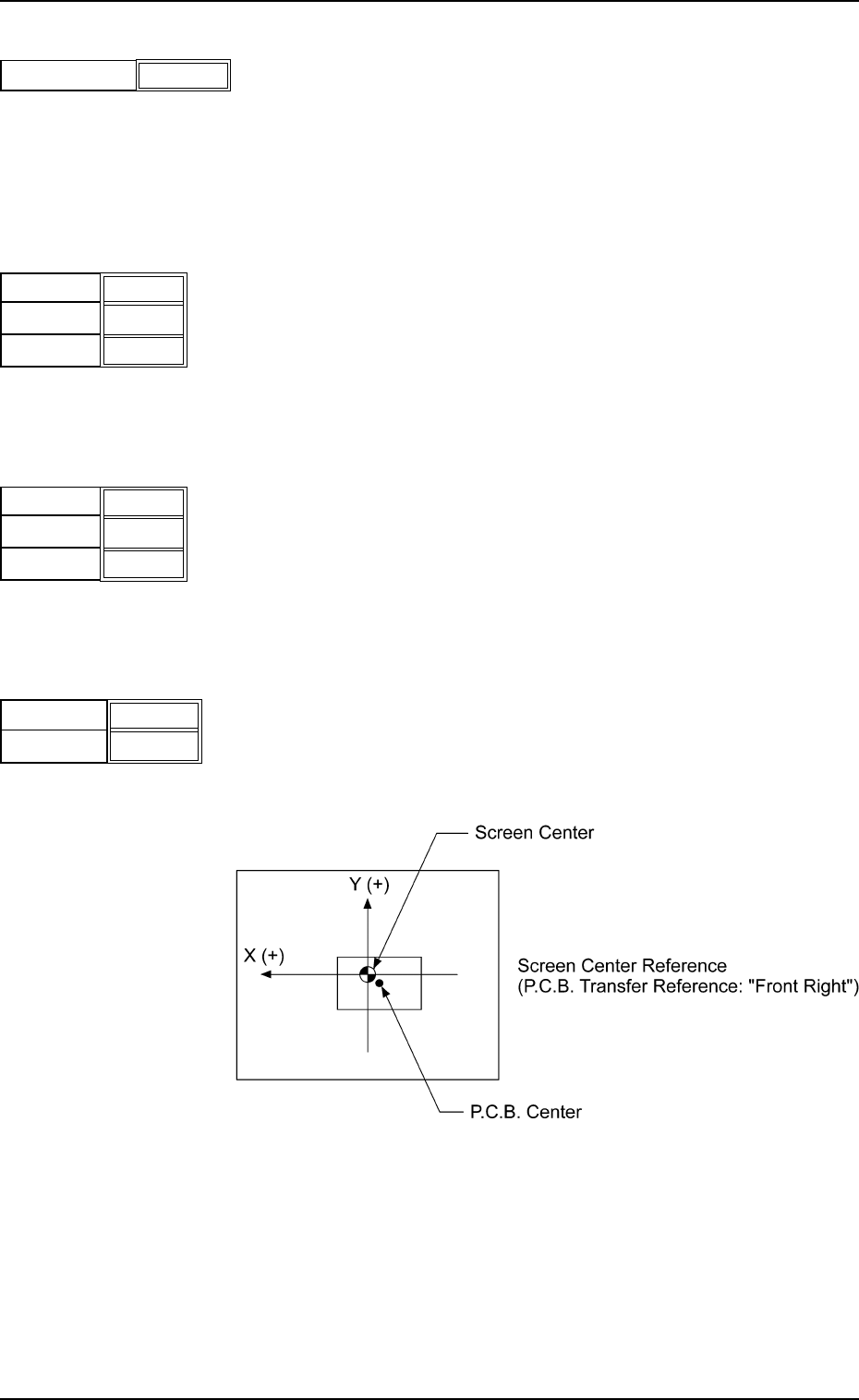
(14) Screen Offset [mm]
When the reference coordinates of the screen are changed
from the design values, set parameters as the offset values.
Unit : mm
X
Y
Fig.3B21
+ 0.0
+ 00.0
Separation Distance [mm]
0.5
Fig.3B18
X [mm]
Y [mm]
+ 0.000
θ [ ° ]
+ 0.000
+ 0.000
Fig.3B20
X [mm]
Y [mm]
+ 0.000
θ [ ° ]
+ 0.000
+ 0.000
Fig.3B19
Fig. 3B22
Data Input Range
X : ±5.0
Y : ±99
Tg0699-PM-D2
1.2 Operation Data
0207-001 Chapter 1 2-8
1.2.3 PCB Backup
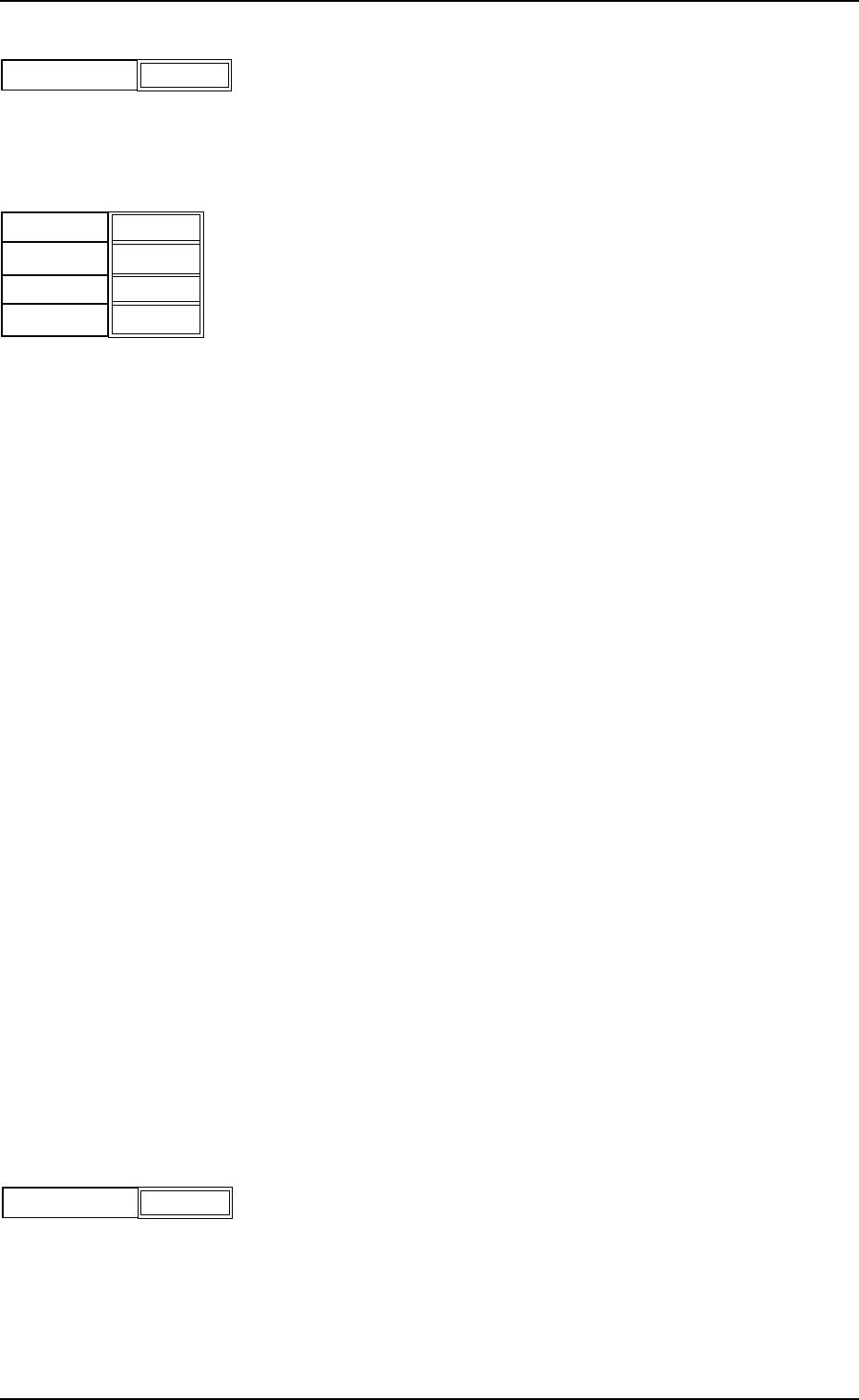
(1) Chuck Stage Select
Select the method to fix the P.C.B. on the table chute.
The specified data is used to determine the P.C.B. fixing
method of the P.C.B. positioning stage.
Backup Jig : This specifies the method which uses
the backup jig.
Support Pin : This specifies the method which uses
the P.C.B. support pins.
Vacuum Pick-Up : Designate the vacuum pick-up mode.
The mechanism which clamps the PCB
from direction Y, is performed.
Vacuum Pick-Up : Designate the vacuum pick-up mode.
(Without Clamping) The mechanism which clamps the PCB
from direction Y, is not performed.
Select one of the options correctly according to the
settings of the mechanism section. Otherwise, the
macine will malfunction.
(2) PCB Warpage Protection
It can be selected whether or not the P.C.B. warpage protec-
tion function should be used to correct the warpage of the
P.C.B.
Select "ON" in normal cases.
When "OFF" is selected, transfer of overlapped
P.C.B.’s cannot be detected.
(3) Vacuum Release Mode
Select time when the picked P.C.B. should be released.
Before : The picked P.C.B. is released before printing opera-
tion.
After : The picked P.C.B. is released after printing opera-
tion.
Select "After" in normal cases.
When a P.C.B. has a lot of through holes and the machine
performs the printing operation with the P.C.B. being picked
up, solder paste may ooze out to the underside of the screen.
In this case, "Before" should be selected.
Chuck Stage Select
Backup Jig
Fig.3B23
PCB Warpage Protection
ON
Fig.3B24
Vacuum Release Mode
Before
Fig.3B25
Tg0699-PM-D2
0207-001 Chapter 1 2-9
1.2 Operation Data
(4) Vacuum Rel. Wait Time
Set the waiting time during which the picked P.C.B. is released
and the backup table descends.
Unit : seconds
(5) PCB Clamp Offset
The backup table ascends to the position where a P.C.B. is
chucked.
It starts ascending again after the P.C.B. horizontal clamping
unit has chucked the P.C.B.
When thin P.C.B.’s are used and chuck errors occur, enter a
value as timing with which a P.C.B. is chucked and the backup
table starts ascending again and a value that represents the
position where the P.C.B. horizontal clamping unit starts to
chuck the P.C.B.
Timing [sec] : Enter a value that represents the
timing with which the backup starts
ascending again after it has stopped.
Unit : seconds
Position [mm] : Enter a value that represents the
changed dimension based on the
current position.
Unit : mm
When a minus (-) value is entered,
the height for chucking start can be
changed.
Bef.Clamp Bkup Spd. : The ascending speed of the backup
table can be set in the range of 10
steps (Full Speed to 90%Down)
before the P.C.B. is clamped.
Unit : %
Aft.Clamp Bkup Spd. : The ascending speed of the backup
table can be set in the range of 10
steps (Full Speed to 90%Down) after
the P.C.B. is clamped.
Unit : %
(6) P.C.B. Stopper Offset Y
Set the offset in the Y direction of the stopper that is used to
stop the P.C.B. in the table chute section.
Unit : mm
When the offset is "0" (zero), the P.C.B. stopper is located at
the center of the P.C.B. end plane.
Specify the offset when there is a cutout, etc., at the center of
the P.C.B. end plane.
Fig.3B26
Vacuum Rel. Wait Time
[sec]
0.0
Fig.3B27
Timing [sec]
Position [mm]
0.00
+0.0
Bef.Clamp
Bkup Spd.
Aft.Clamp
Bkup Spd.
Full Speed
Full Speed
P.C.B. Stopper Offset Y
[mm]
+000
Fig.3B28