2OM-1088-002.pdf - 第82页
Tg0699-PM-D2 0207-001 Chapter 1 2-23 1.2 Operation Data Specification of Lines extended from a Pad Mark or a Through Hole Unit : mm The wires from both the through hole and pad mark are each at an angle of 45° and only o…
Tg0699-PM-D2
0207-001 Chapter 1 2-22
1.2 Operation Data
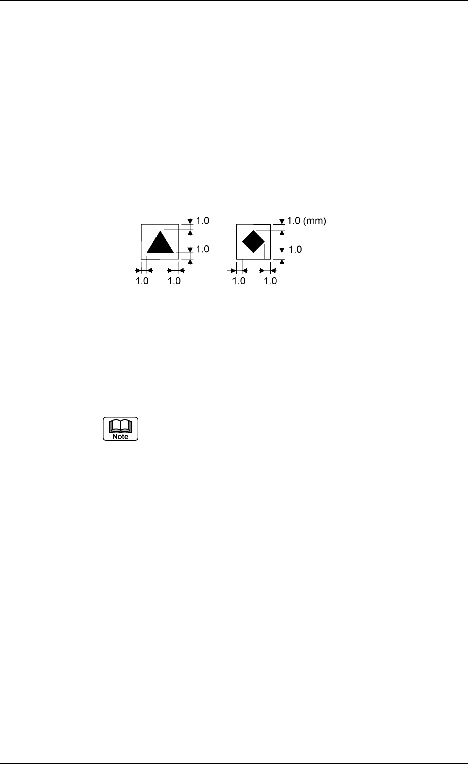
Regulations regarding Mark Surroundings
• A fiducial mark should make ample contrast with the surround-
ings. (Preven-tion of False Recognition)
• The shape of P.C.B. (a cutout, a punched hole), the external
elements (light reflected from a structure, light emitted from an
external device, etc.,) may sometimes interfere with recognition.
(Consult our marketing department or salse agency for details.)
• A copper leaf, a resist, a coating, a silk print, and a punched
hole should not exist in the range of 1.0 mm in both X and Y
directions from the outermost edges of a fiducial mark. They
may cause false recognition.
• Anything resembling a pattern similar to a fiducial mark should
not exist in the designated recognition area. If one exists, it may
cause false recogni-tion.
Refer to "Chapter 2" in "Volume 1" for the material of
the screen plate and the settings of screen fiducial
marks.
Fig. 3B49
Tg0699-PM-D2
0207-001 Chapter 1 2-23
1.2 Operation Data
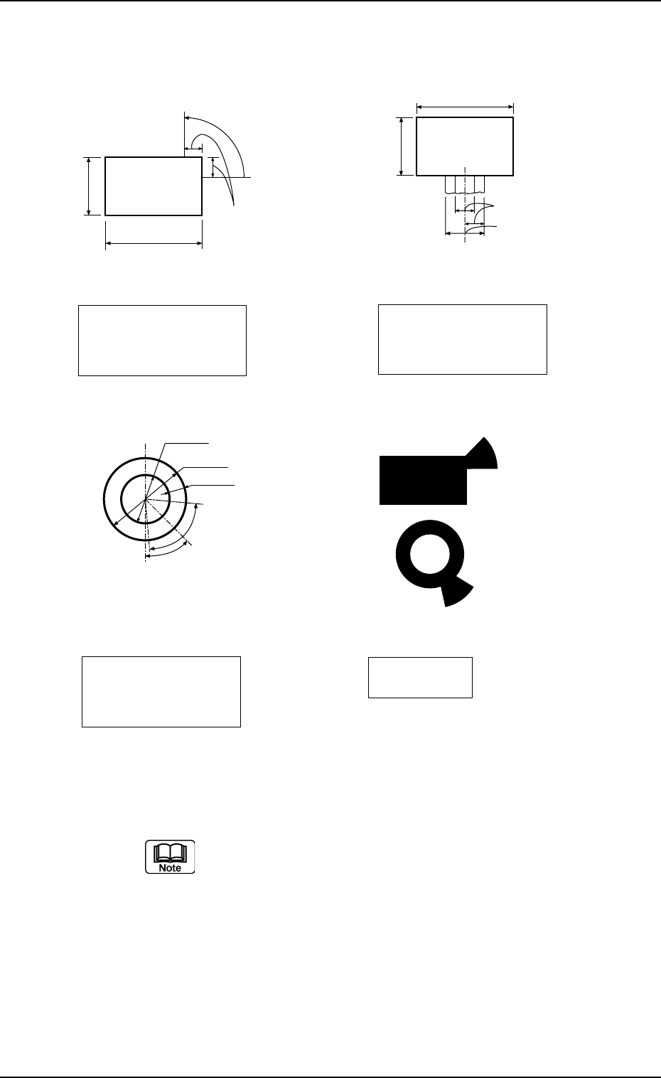
Specification of Lines extended from a Pad Mark or a Through Hole
Unit : mm
The wires from both the through hole and pad mark are each at an
angle of 45° and only one wire is used for each through hole and
pad mark. Consult our marketing department or sales agency for
details of size, etc.
Fig. 3B50
(Front Side of Machine㧕
Examples of
Land Locations
Range between Lines
and Tangential Lines
0.5 to 2.0
0.5 to 2.0
1/3 of
Shorter Side
(Front Side of Machine㧕
Pad Mark 45q
Range of Land Location
in Increments of 45qHQT
Pad mark
1.0 to 2.0
Min.0.25
80q
(Range between
Lines and
Tangential Lines)
0.5 to 1.5
45q
(Front Side of Machine㧕
Range of Land Location
for Through Hole
(45qat the bottom right
of the hole
Range between
Lines and
Tangential Lines
0.5 to 2.0
1/3 of Shorter Side
(Front Side of Machine㧕
Pad Mark 90q
Range of Land Location
in Increments of 45qHQT
Pad mark
0.5 to 2.0
Tg0699-PM-D2
1.2.7 Setup Data
It can be determined whether or not each unit should be set up.
The settings can be changed using the menus in the "ALL
PROD. CHG." window.
(1) All Conveyor Setup
It can be determined whether or not the L conveyor width, the
table chute conveyor width, and the R conveyor width should
be set up according to the P.C.B. dimension Y (vertical).
OFF : Each conveyor width is not set up.
ON : Each conveyor width is set up.
(2) Two Camera Auto Calib.
It can be determined whether or not the two camera automatic
calibration should be performed, using the "ALL PROD. CHG."
menu.
OFF : The machine does not perform the setup operation for
the two camera automatic calibration.
ON : The machine performs the setup operation for the two
cam-era automatic calibration.
The two camera automatic calibration function works
to automatically correct the positional coordinates of
the P.E.C. and screen recognition cameras.
(3) Screen Recog
It can be determined whether or not the screen recognition
should be performed, using the "ALL PROD. CHG." menu.
OFF : The machine does not perform any setup operation for
screen recognition.
ON : The machine performs the setup operation for screen
rec-ognition.
(4) Prntng Prs. Adj
Set whether or not the printing pressure is adjusted, using the
"Overall Setup" menu.
OFF : The printing pressure is not adjusted.
ON : The printing pressure is adjusted.
All Conveyor Setup
ON
Fig.3B51
Two Camera Auto Calib.
ON
Fig.3B52
Screen Recog
ON
Fig.3B53
0207-001 Chapter 1 2-24
1.2 Operation Data
Prntng Prs. Adj
ON
Fig.3B54