00198442-04_UM_TX-V2_EN.pdf - 第117页
Instruction manual SIPLACE TX 3 Technical data and assemblies From software version 714.0 12/2020 3.5 Placement head 117 3.5 Placement head 3.5.1 SIPLACE SpeedS tar C&P20 P2 on the SIPLACE TX The SIPLACE TX uses th e…
3 Technical data and assemblies Instruction manual SIPLACE TX
3.4 Overview of the modules From software version 714.0 12/2020
116
3.4 Overview of the modules
3
3
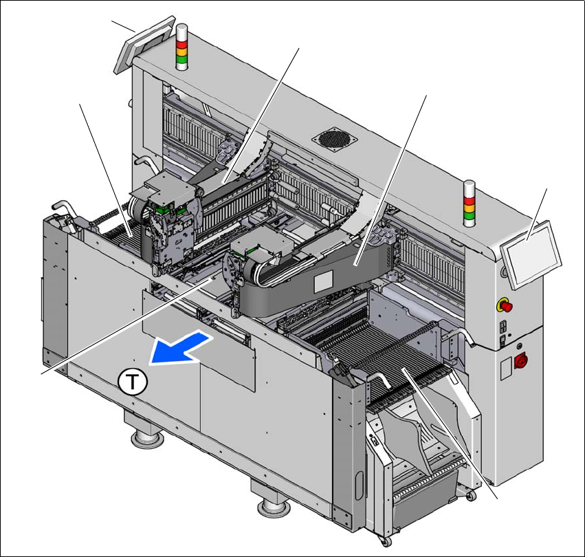
Fig. 3.4 - 1 Component overview - example of SIPLACE TX2i
(1) Location 1 with component trolley, tape cutter, empty tape duct
(2) Monitor at location 1
(3) Gantry at location 1 (placement head, depending on configuration)
(4) Gantry at location 2 (placement head, depending on configuration)
(5) Monitor at location 2
(6) Location 2 with component trolley, tape cutter, empty tape duct
(7) Board conveyor
(T) Direction of PCB transport
(1)
(3)
(4)
(6)
(2)
(7)
(5)

Instruction manual SIPLACE TX 3 Technical data and assemblies
From software version 714.0 12/2020 3.5 Placement head
117
3.5 Placement head
3.5.1 SIPLACE SpeedStar C&P20 P2 on the SIPLACE TX
The SIPLACE TX uses the SIPLACE SpeedStar C&P20 P2 for top placement performance.
3
CAUTION
Always take hold of the handle to push the placement head
The placement head may only be moved by pushing manually against the handle provid-
ed.
3 Technical data and assemblies Instruction manual SIPLACE TX
3.5 Placement head From software version 714.0 12/2020
118
3.5.1.1 Overview
3
3
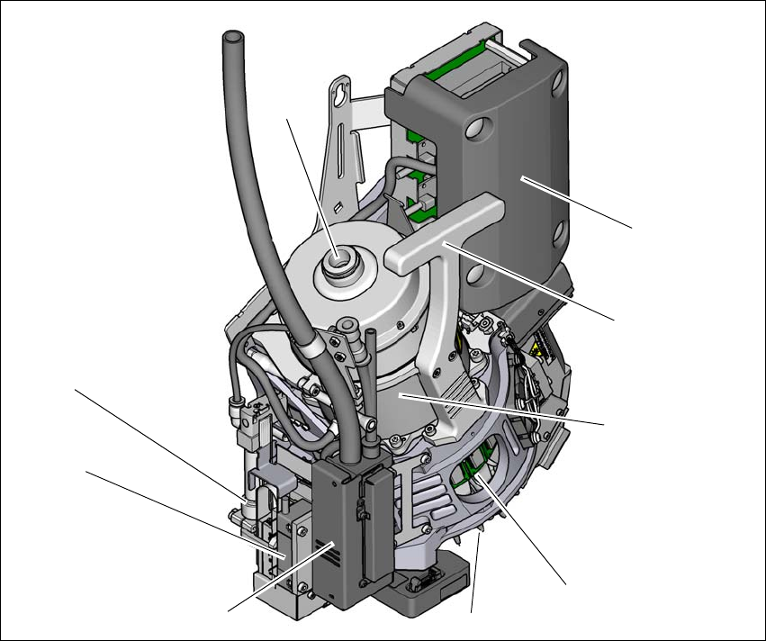
Fig. 3.5 - 1 SIPLACE SpeedStar - overview
(1) Connection for the holding circuit of the vacuum pump
(2) "Intermediate distributor" board (under the cover)
(3) Handle
(4) Star motor
(5) DP drive
(6) Nozzle
(7) Pressure control valve
(8) Z motor (linear motor)
(9) Return cylinder
(5)
(1)
(7)
(2)
(3)
(4)
(6)
(8)
(9)