00198442-04_UM_TX-V2_EN.pdf - 第122页
3 Technical data and assemblie s Instruction manual SIPLACE TX 3.5 Placement head From software version 714.0 12/2020 122 3.5.2.2 T echnical dat a for SIPLACE SpeedSt ar (C&P20 M3) on SIPLA CE TX2 m / TX2i m 3 SIPLAC…
Instruction manual SIPLACE TX 3 Technical data and assemblies
From software version 714.0 12/2020 3.5 Placement head
121
3.5.2.1 Overview
3
3
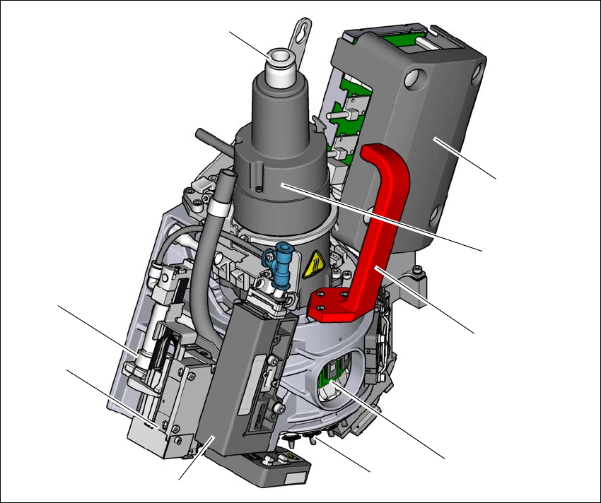
Fig. 3.5 - 2 SIPLACE SpeedStar C&P20 M3- overview
(1) Connection for the holding circuit of the vacuum pump
(2) "Vacuum sensor holding circuit" board (under the cover)
(3) Star motor
(4) Handle
(5) DP drive
(6) Nozzle
(7) Pressure control valve
(8) Z motor (linear motor)
(9) Return cylinder
(5)
(1)
(7)
(2)
(3)
(4)
(6)
(8)
(9)
3 Technical data and assemblies Instruction manual SIPLACE TX
3.5 Placement head From software version 714.0 12/2020
122
3.5.2.2 Technical data for SIPLACE SpeedStar (C&P20 M3) on SIPLACE TX2 m / TX2i m
3
SIPLACE SpeedStar (C&P20 M3)
With component camera
type 48 (Standard)
With component camera
type 49 (Optional)
Component range
*a
*)a Please note that the placeable component range is also affected by the pad geometry, the customer-specific
standards, the component packaging tolerances and the component tolerances.
0.12 mm x 0.12 (0201 metric) to 2220, Melf, SOT, SOD, Bare-Die,
Flip-Chip
Component spec.
Max height
Max. height
*b
Min. lead pitch
Min. lead width
Min. ball pitch
Min. ball diameter
Min. dimensions
Max. dimensions
Max. weight
*)b The maximum component height of 4 mm is only possible with the machine type SIPLACE TX2i m 4 mm.
2 mm
4 mm
70 µm
30 µm
100 µm
50 µm
120 µm x 120 µm
8.2 mm x 8.2 mm
1 g
2 mm
*c
4 mm
*c
50 µm
25 µm
50 µm
25 µm
80 µm x 80 µm
8.2 mm x 8.2 mm
1 g
*)c Due to the small area of focus of ±0.3 mm, this camera is only recommended if this particular camera res-
olution is required for the components. The requirements for component camera type 49 are achieved in the
±0.3mm range. The component camera type 49 achieves the performance rating of component camera type
48 in the ±0.6mm range. The nozzle length needs to be adjusted in accordance with the area of focus and
component thickness.
Set-down force 1.3 N ± 0.5 N (default value)
0.5 N to 4.5 N
Touchless Placement
Nozzle types 60xx 60xx
X/Y accuracy
*d
Standard
With "accuracy class"
*e
*)d The benchmark and accuracy values are measured during the machine acceptance tests and correspond
to the conditions set out in the ASM scope of service and supply.
*)e Setting the accuracy class in the SIPLACE Pro Component Shape Editor or Placement Position Editor. 15
µm only possible with PCBs up to a size of 250 mm x 100 mm.
± 25 µm/3σ
± 20 µm/3σ
± 15 µm/3σ
± 25 µm/3σ
± 20 µm/3σ
± 15 µm/3σ
Angular accuracy ± 0.2° / 3σ ± 0.2° / 3σ
Illumination level 5 5
Instruction manual SIPLACE TX 3 Technical data and assemblies
From software version 714.0 12/2020 3.5 Placement head
123
3.5.3 Sensor for the component reject bin
The sensor for the component reject bin monitors whether the reject bin is seated correctly in its
mount.
– If the reject bin was not inserted correctly, the placement machine cannot be started.
– If the reject bin jumps out of its mount during the placement process, the placement machine
will be stopped immediately to avoid a head crash.
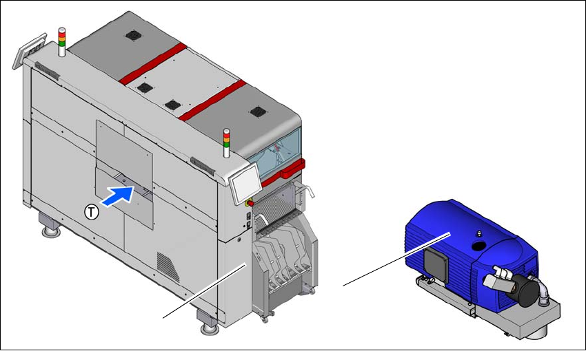
3.5.4 Vacuum pump
The vacuum pump for the SIPLACE SpeedStar is fitted behind the cover at location 1, in the ma-
chine frame. There are two types available:
– Vacuum pump VX4.25
– Vacuum pump VX4.25/0-47 IE3
3.5.4.1 Overview - type VX4.25
Item no. 03128463-xx Vacuum pump VX4.25
3
Fig. 3.5 - 3 Overview - vacuum pump
(1) Installation location for vacuum pump
(2) Vacuum pump VX 4.25
(2)
(1)