00198442-04_UM_TX-V2_EN.pdf - 第123页
Instruction manual SIPLACE TX 3 Technical data and assemblies From software version 714.0 12/2020 3.5 Placement head 123 3.5.3 Sensor for the component reject bin The sensor for the com ponent re je ct bin monitors wheth…
3 Technical data and assemblies Instruction manual SIPLACE TX
3.5 Placement head From software version 714.0 12/2020
122
3.5.2.2 Technical data for SIPLACE SpeedStar (C&P20 M3) on SIPLACE TX2 m / TX2i m
3
SIPLACE SpeedStar (C&P20 M3)
With component camera
type 48 (Standard)
With component camera
type 49 (Optional)
Component range
*a
*)a Please note that the placeable component range is also affected by the pad geometry, the customer-specific
standards, the component packaging tolerances and the component tolerances.
0.12 mm x 0.12 (0201 metric) to 2220, Melf, SOT, SOD, Bare-Die,
Flip-Chip
Component spec.
Max height
Max. height
*b
Min. lead pitch
Min. lead width
Min. ball pitch
Min. ball diameter
Min. dimensions
Max. dimensions
Max. weight
*)b The maximum component height of 4 mm is only possible with the machine type SIPLACE TX2i m 4 mm.
2 mm
4 mm
70 µm
30 µm
100 µm
50 µm
120 µm x 120 µm
8.2 mm x 8.2 mm
1 g
2 mm
*c
4 mm
*c
50 µm
25 µm
50 µm
25 µm
80 µm x 80 µm
8.2 mm x 8.2 mm
1 g
*)c Due to the small area of focus of ±0.3 mm, this camera is only recommended if this particular camera res-
olution is required for the components. The requirements for component camera type 49 are achieved in the
±0.3mm range. The component camera type 49 achieves the performance rating of component camera type
48 in the ±0.6mm range. The nozzle length needs to be adjusted in accordance with the area of focus and
component thickness.
Set-down force 1.3 N ± 0.5 N (default value)
0.5 N to 4.5 N
Touchless Placement
Nozzle types 60xx 60xx
X/Y accuracy
*d
Standard
With "accuracy class"
*e
*)d The benchmark and accuracy values are measured during the machine acceptance tests and correspond
to the conditions set out in the ASM scope of service and supply.
*)e Setting the accuracy class in the SIPLACE Pro Component Shape Editor or Placement Position Editor. 15
µm only possible with PCBs up to a size of 250 mm x 100 mm.
± 25 µm/3σ
± 20 µm/3σ
± 15 µm/3σ
± 25 µm/3σ
± 20 µm/3σ
± 15 µm/3σ
Angular accuracy ± 0.2° / 3σ ± 0.2° / 3σ
Illumination level 5 5
Instruction manual SIPLACE TX 3 Technical data and assemblies
From software version 714.0 12/2020 3.5 Placement head
123
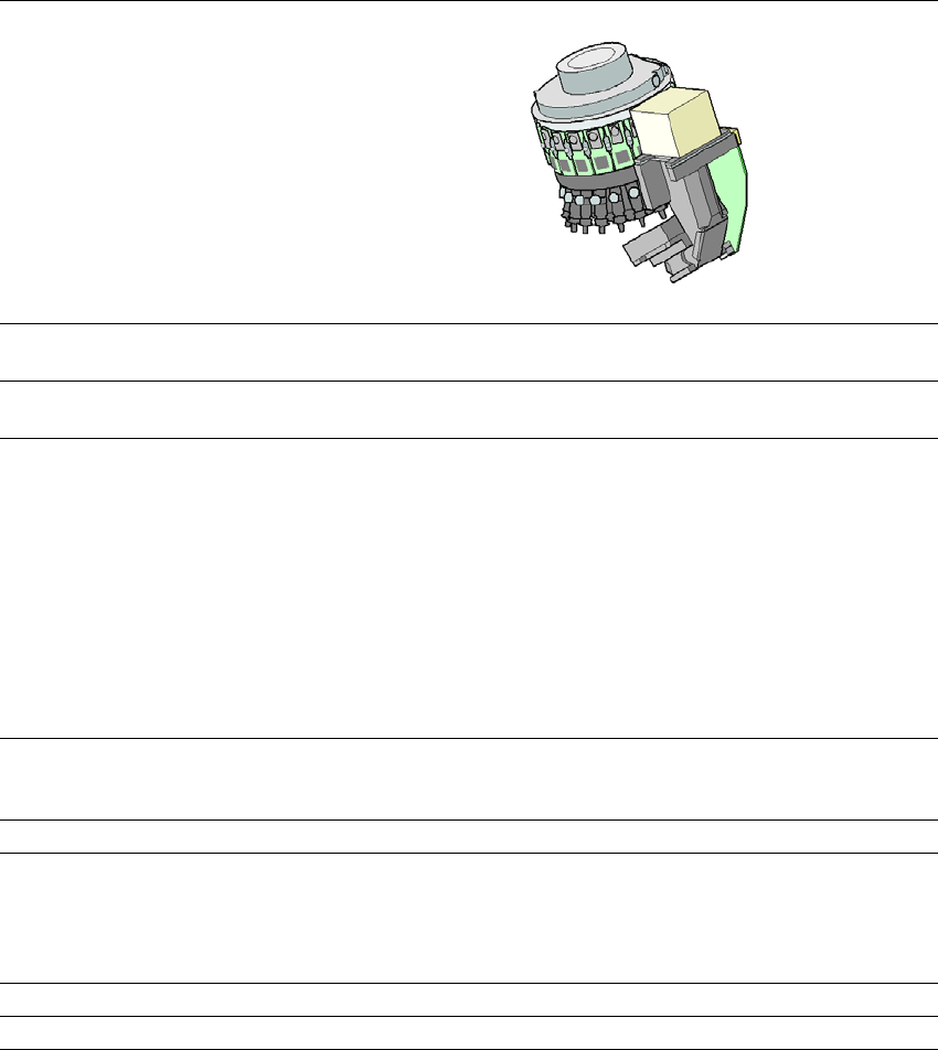
3.5.3 Sensor for the component reject bin
The sensor for the component reject bin monitors whether the reject bin is seated correctly in its
mount.
– If the reject bin was not inserted correctly, the placement machine cannot be started.
– If the reject bin jumps out of its mount during the placement process, the placement machine
will be stopped immediately to avoid a head crash.
3.5.4 Vacuum pump
The vacuum pump for the SIPLACE SpeedStar is fitted behind the cover at location 1, in the ma-
chine frame. There are two types available:
– Vacuum pump VX4.25
– Vacuum pump VX4.25/0-47 IE3
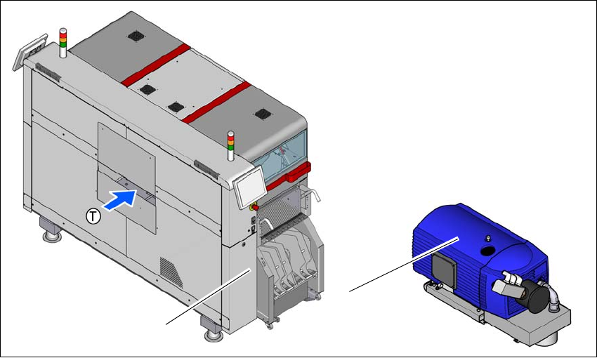
3.5.4.1 Overview - type VX4.25
Item no. 03128463-xx Vacuum pump VX4.25
3
Fig. 3.5 - 3 Overview - vacuum pump
(1) Installation location for vacuum pump
(2) Vacuum pump VX 4.25
(2)
(1)
3 Technical data and assemblies Instruction manual SIPLACE TX
3.5 Placement head From software version 714.0 12/2020
124
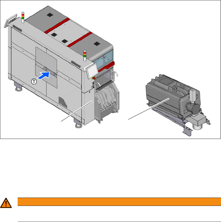
3.5.4.2 Overview - type VX4.25/0-47 IE3
Item no. 03224400-xx Vacuum pump VX4.25/0-47 IE3
3
Fig. 3.5 - 4 Overview - vacuum pump
(1) Installation location for vacuum pump
(2) Vacuum pump VX 4.25 IE3
3.5.4.3 Safety instructions for vacuum pumps
3
(2)
(1)
WARNING
Please observe the safety instructions in the vacuum pump instruction manual sup-
plied.