00198442-04_UM_TX-V2_EN.pdf - 第150页
3 Technical data and assemblie s Instruction manual SIPLACE TX 3.7 PCB conveyor system From software version 714.0 12/2020 150 3.7.6 PCB camera T wo diff erent types of PCB cameras can be used: – PCB camera, type 34 GigE…
Instruction manual SIPLACE TX 3 Technical data and assemblies
From software version 714.0 12/2020 3.7 PCB conveyor system
149
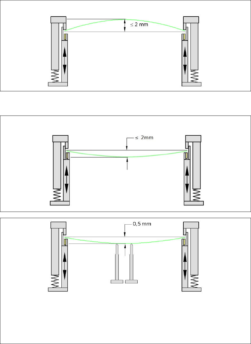
3.7.5.2 PCB warpage during placement
3
3
Changes in the surface position are automatically applied by the functions for learning the height.
3
3
PCB warpage up, max. 2.5 mm
PCB warpage down, max. 2.5 mm
PCB support
To avoid impairing the placement quality and speed, we recommend using a PCB support e.g.
Smart Pin Support so that the PCB warpage downwards does not exceed 0.5 mm.
3 Technical data and assemblies Instruction manual SIPLACE TX
3.7 PCB conveyor system From software version 714.0 12/2020
150
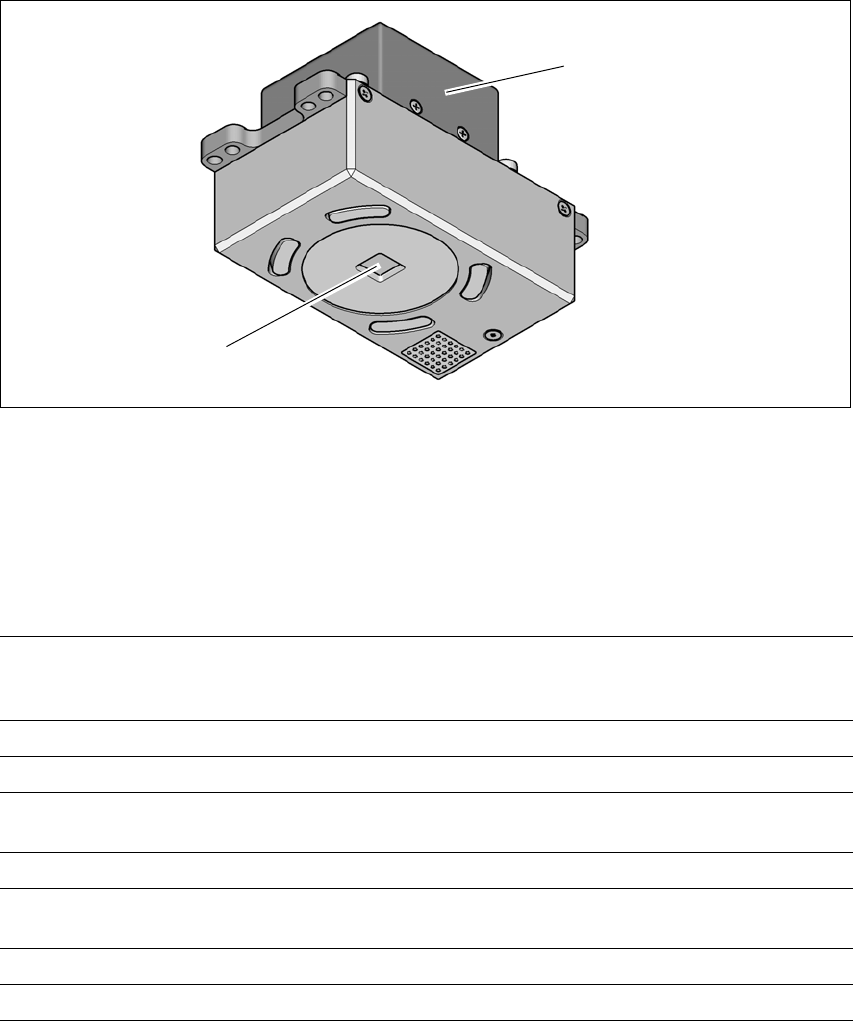
3.7.6 PCB camera
Two different types of PCB cameras can be used:
– PCB camera, type 34 GigE
– PCB camera, type 54 GigE
3.7.6.1 Structure
3
Fig. 3.7 - 4 PCB camera
(1) Camera amplifier
(2) PCB camera lens and illumination
3.7.6.2 Technical data
3
(1)
(2)
PCB fiducials Up to 3 (subpanels and multiple panels)
Up to 6 for the Long board option (Optional PCB fiducials are
output by the optimization).
Local fiducials Up to 2 per PCB (may be of different type)
Library memory Up to 255 fiducial types per subpanel
Image analysis Edge detection method (Singular feature) based on grayscale
values
Illumination type Front-illumination (3 levels, programmable as required)
Detection time per
fiducial/bad fiducial
20 ms - 200 ms
Field of vision 5.78 mm x 5.78 mm
Distance from the focus plane 28 mm

Instruction manual SIPLACE TX 3 Technical data and assemblies
From software version 714.0 12/2020 3.7 PCB conveyor system
151
3.7.6.3 Fiducial criteria
3
Locate 2 fiducials
Locate 3 fiducials
X-/Y-position, rotation angle, mean PCB distortion
Additional: shearing, distortion separately in X and Y direction
Fiducial shapes Synthetic fiducials: circle, cross, square, rectangle, diamond,
circular, square and rectangular contours, double cross
Pattern: any
Fiducial surface
Copper
Tin
Without oxidation and solder resist
Warp ≤ 1/10 of structure width, both with good contrast to
environment
Dimensions of synthetic fiducials
Min. X/Y size for circle
*a
and rectangle:
Min. X/Y size for annulus and rectangle:
Min. X/Y size for cross:
Min. X/Y size for double-cross:
Min. X/Y size for rhombus:
Min. frame width for annulus and rectangle:
Min. bar width / bar distance for cross, double-cross:
Max. X/Y size for all fiducial shapes:
Max. bar width for cross, double-cross:
Min. tolerances, general:
Max. tolerances, general:
0.25 mm
0.3 mm
0.3 mm
0.5 mm
0.35 mm
0.1 mm
0.1 mm
3 mm
1.5 mm
2% of nominal dimension
20% of nominal dimension
Dimensions of patterns
Min. size
Max. size
0.5 mm
3 mm
Fiducial environment Clearance around reference fiducial not necessary if there is no
similar fiducial structure in the search area.
*)a Observe the following with the SIPLACE TX2 V2 m, TX2i V2 m and TX2i V2 m 4 mm: To ensure high pro-
duction quality of printed circuit boards, a minimum x/y size of 0.075 mm is permitted for circular fiducials
under the following conditions:
There are no other objects with a size of + 0.2 mm which are visible in the rectangular fiducial search area.
Example: Circular fiducials with an x/y size of 0.075 mm need a search area without visible objects of:
0.075 mm + 0.2 mm = 0.275 mm.