00198442-04_UM_TX-V2_EN.pdf - 第164页
3 Technical data and assemblie s Instruction manual SIPLACE TX 3.9 Component trolley From software version 714.0 12/2020 164 3.9 Component trolley T wo SIPLACE TX compo nent trolleys can be do cked onto SIPLACE TX p lace…
Instruction manual SIPLACE TX 3 Technical data and assemblies
From software version 714.0 12/2020 3.8 SIPLACE tape feeder modules for SIPLACE TX
163
3.8.5.2 Safety instructions
3.8.5.3 Technical data
3
3
3
3
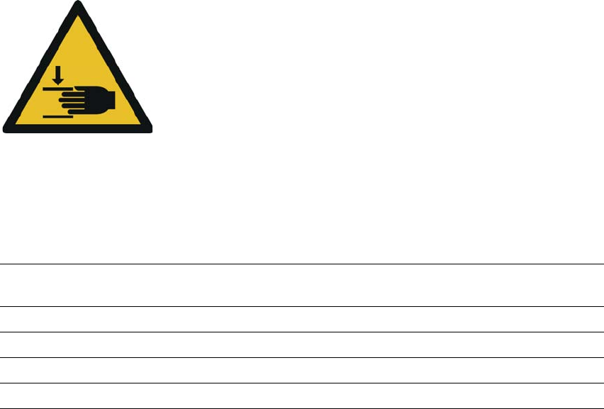
Warning about hand injuries
There is a risk of injury to hands when folding the extender arm up
into the park position.
When folding up the extender arm, make sure that you do not
trap your hand between the extender arm and the
S
IPLACE PowerConnector X.
Length 648.4 mm (folded in)
866.9 mm (folded out)
Width 34.4 mm
Height 188.4 mm
Occupied locations 3
Weight 3.2 kg
3 Technical data and assemblies Instruction manual SIPLACE TX
3.9 Component trolley From software version 714.0 12/2020
164
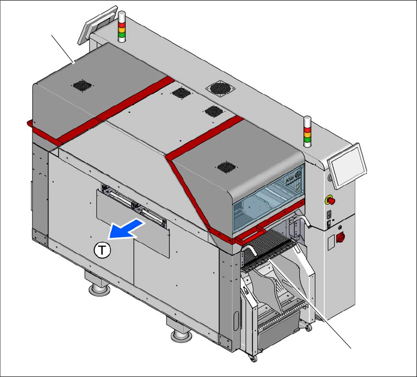
3.9 Component trolley
Two SIPLACE TX component trolleys can be docked onto SIPLACE TX placement machines.
3
Fig. 3.9 - 1 Component trolley locations
(1) Location 1
(2) Location 2 with optional 7" tape reel holder
(T) Direction of PCB transport
The component trolleys are stand-alone modules that can be set up with feeders at an external
setup area. This means that the production process only has to be interrupted briefly in order to
change the component trolley. The component trolley has 5 holders in total. Each tape reel holder
can accommodate 2 tape reels, so that up to ten 13" (optional 7") tape reels can be positioned
above the tape container.
(2)
(1)
Instruction manual SIPLACE TX 3 Technical data and assemblies
From software version 714.0 12/2020 3.9 Component trolley
165
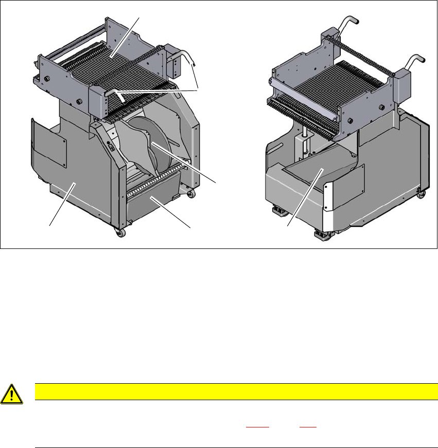
3.9.1 Structure
The component trolley essentially consists of the chassis, the changeover table for holding the
feeder modules, the tape reel container and the waste tape container. The pullout waste tape con-
tainer can be found beneath the chassis. The cut waste tape travel down a chute into the waste
tape container, which must be emptied as it fills up.
3
Fig. 3.9 - 2 Component trolley, SIPLACE TX-Series, front and rear view
(1) Changeover table with 40 tracks
(2) Handles
(3) Waste tape container
(4) Tape reel container with 13" tape reels
(5) Chassis
3
CAUTION
Observe the safety instructions!
Observe the safety instructions in section 5.8.2, page 246 when you pull the tape re-
ject bin out of the component trolley.
(1)
(2)
(3)
(4)
(3)
(5)