00198442-04_UM_TX-V2_EN.pdf - 第166页
3 Technical data and assemblie s Instruction manual SIPLACE TX 3.9 Component trolley From software version 714.0 12/2020 166 3 3 3 3.9.2 T echnical dat a 3 3 CAUTION Risk of breaking handles! Risk of breaking handles whe…
Instruction manual SIPLACE TX 3 Technical data and assemblies
From software version 714.0 12/2020 3.9 Component trolley
165
3.9.1 Structure
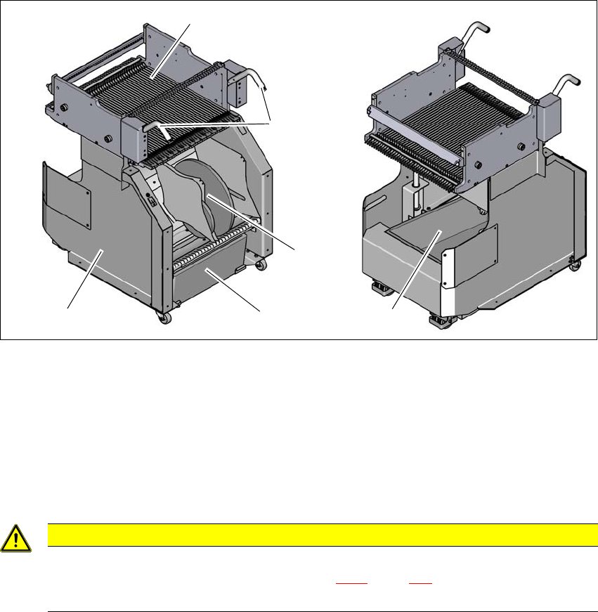
The component trolley essentially consists of the chassis, the changeover table for holding the
feeder modules, the tape reel container and the waste tape container. The pullout waste tape con-
tainer can be found beneath the chassis. The cut waste tape travel down a chute into the waste
tape container, which must be emptied as it fills up.
3
Fig. 3.9 - 2 Component trolley, SIPLACE TX-Series, front and rear view
(1) Changeover table with 40 tracks
(2) Handles
(3) Waste tape container
(4) Tape reel container with 13" tape reels
(5) Chassis
3
CAUTION
Observe the safety instructions!
Observe the safety instructions in section 5.8.2, page 246 when you pull the tape re-
ject bin out of the component trolley.
(1)
(2)
(3)
(4)
(3)
(5)
3 Technical data and assemblies Instruction manual SIPLACE TX
3.9 Component trolley From software version 714.0 12/2020
166
3
3
3
3.9.2 Technical data
3
3
CAUTION
Risk of breaking handles!
Risk of breaking handles when transporting the component trolley.
When transporting the component trolley, do not lift it by its handles.
Only use the handles to push the component trolley.
Use a fork-lift if you want to transport the component trolley or lift it off the pallet.
CAUTION
Risk of component trolley tilting
There is a risk of tilting when moving the component trolley over obstacles and sloping
surfaces.
Do not move the component trolley over obstacles and do not bump it against ob-
jects.
When moving along sloping surfaces, make sure that the component trolley does not
roll away by itself, so that it could tip over.
PLEASE NOTE
All component trolleys must be docked onto the
placement machine in order to operate it.
Fill any free locations with dummy feeder modules as described in
section 2.5.4
, page 92.
Length x width 727 mm x 592 mm
Height of the changeover table 890 mm for 900 mm PCB conveyor height
920 mm for 930 mm PCB conveyor height
940 mm for 950 mm PCB conveyor height
Number of locations 40 (Smart Feeder 8 mm X tape feeder mod-
ule)
Weight
Without feeder modules
With feeder module at all locations
80 kg
140 kg
Tape reel diameter
Tape container
In two rows as an option
to 330.2 mm (13")
to 177.8 mm (7")
Instruction manual SIPLACE TX 3 Technical data and assemblies
From software version 714.0 12/2020 3.9 Component trolley
167
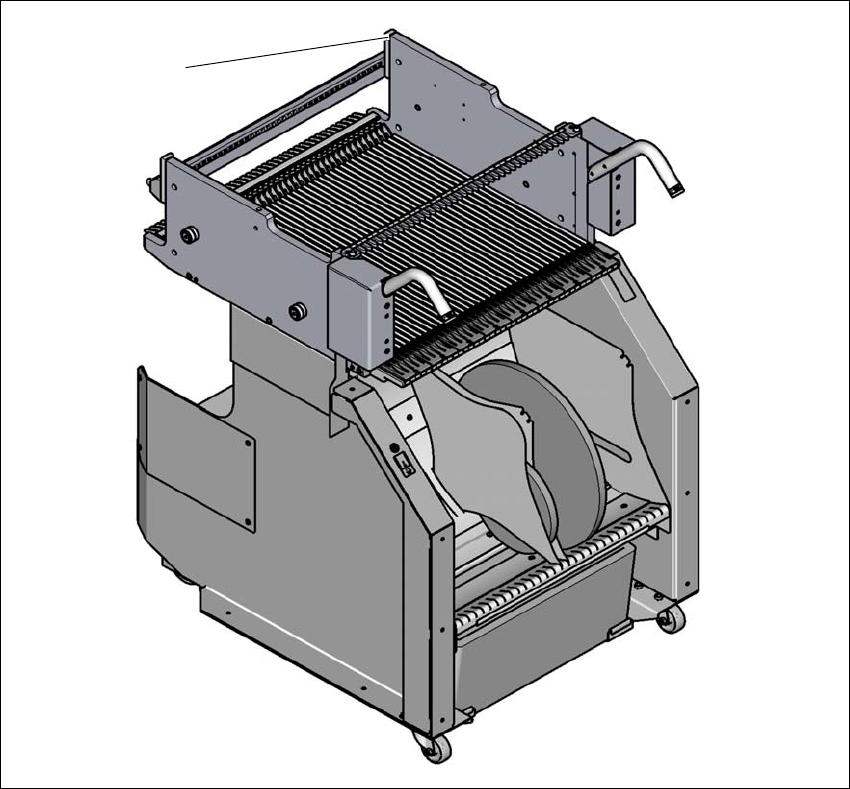
3.9.3 Fiducials on the SIPLACE TX-Series component trolley
3
Fig. 3.9 - 3 Fiducials on the SIPLACE TX-Series component trolley
(1) Fiducials on the component trolley
Once the SIPLACE TX component trolley has been docked in, the placement machine measures
the fiducials on the component trolley.
In the case of components with an edge length less than 0.5 mm, meaning 0402 components and
smaller, the position of the component is determined with the tape pocket, when the setup is spec-
ified or when the start button is pressed after the table or feeder has been removed.
(1)