00198442-04_UM_TX-V2_EN.pdf - 第177页
Instruction manual SIPLACE TX 4 Setting up and commissioning From software version 714.0 12/2020 4.2 Configuration when delive red 177 4.2.5.2 Weight of m achine when ready for dispatch The following table contains the w…
4 Setting up and commissioning Instruction manual SIPLACE TX
4.2 Configuration when delivered From software version 714.0 12/2020
176
4.2.5 Transporting the placement machine in the shipping crate or on the pallet
4
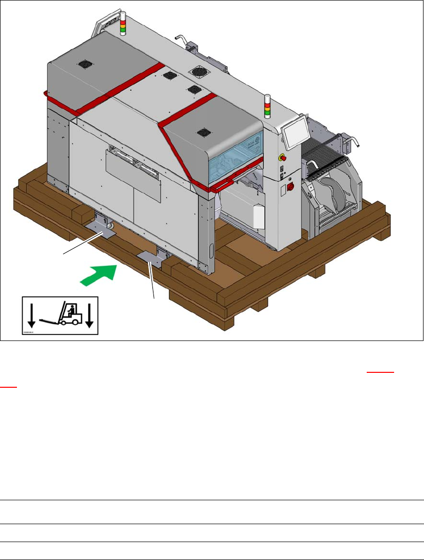
Fig. 4.2 - 2 Transportation crate/pallet - attachment points for transportation with the fork-lift
The transport crate or pallet should preferably only be lifted at the side (item A in fig. 4.2 - 2, page
176
) on which the output end of the machine is located.
Transport the SIPLACE TX on the pallet or in the crate as near as possible to the final site of
use.
4.2.5.1 Shipping packaging dimensions
The dimensions of the pallets and wooden crates are listed in the following table:
4
(A)
1
1
Placement machine (L x W x H)
Pallet 2670mm x 2100mm
Wooden crate 2670 mm x 2100 mm x 1850

Instruction manual SIPLACE TX 4 Setting up and commissioning
From software version 714.0 12/2020 4.2 Configuration when delivered
177
4.2.5.2 Weight of machine when ready for dispatch
The following table contains the weights of the placement machines prepared for dispatch, includ-
ing packaging.
4
4.2.5.3 Transportation equipment for transporting the placement machine in the packaging
Use a fork-lift truck with the following specification to carry the placement machine:
4
Placement machine Dispatch within Europe Dispatch overseas
SIPLACE TX with two component trol-
leys
2350 kg 2600 kg
Fork length Min. 1800 mm
Lifting power Min. 3000 kg
4 Setting up and commissioning Instruction manual SIPLACE TX
4.2 Configuration when delivered From software version 714.0 12/2020
178
4.2.6 Lifting the placement machine off the pallet
4
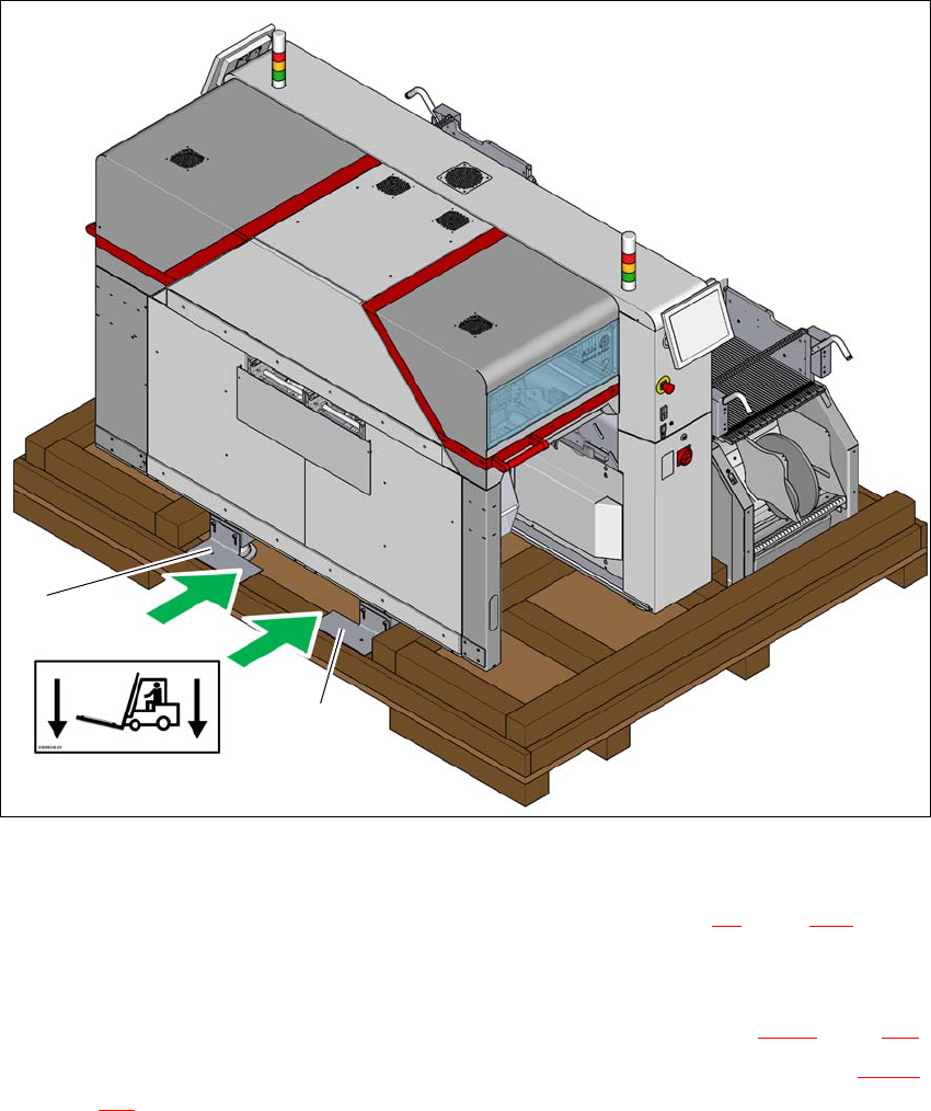
Fig. 4.2 - 3 Contact points for transportation with the fork-lift
(1) Shipping braces with steel spacer
During transportation, always follow the safety instructions in section 4.1, page 171).
Loosen the two shipping braces (1) on the pallet. The two braces and the steel spacers re-
main fitted to the placement machine.
Loosen and remove the shipping braces on the opposite side (item 2 in fig. 4.2 - 1, page 175).
The placement machine may ONLY be lifted with a fork-lift on the side (item A in fig. 4.2 - 3,
page 178
) on which the output end of the machine is located.
(A)
1
1