00198442-04_UM_TX-V2_EN.pdf - 第184页
4 Setting up and commissioning In struction manual SIPLACE TX 4.4 Infrastructure at the installation location From software ve rsion 714.0 12/2020 184 4.4.2.1 Checking the compressed air s upply Check whether the compres…
Instruction manual SIPLACE TX 4 Setting up and commissioning
From software version 714.0 12/2020 4.4 Infrastructure at the installation location
183
4.4.2 Compressed air supply
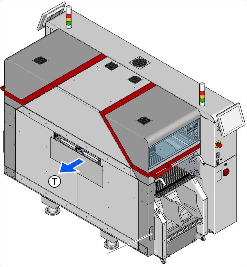
Fig. 4.4 - 1 Position of compressed air supply in the placement machine
(1) Installation position of compressed air supply at location 2
(T) Direction of travel
1

4 Setting up and commissioning Instruction manual SIPLACE TX
4.4 Infrastructure at the installation location From software version 714.0 12/2020
184
4.4.2.1 Checking the compressed air supply
Check whether the compressed air supply complies with the prescribed placement machine spec-
ifications (see table in section 3.2
, page 108).
Record the compressed air characteristics at the installation location.
4
WARNING
Risk of injuries!
Risk of injuries from pressurized compressed air lines.
NEVER detach compressed air lines while they are still pressurized.
Instruction manual SIPLACE TX 4 Setting up and commissioning
From software version 714.0 12/2020 4.4 Infrastructure at the installation location
185
4.4.2.2 Compressed air connection on the placement machine
4
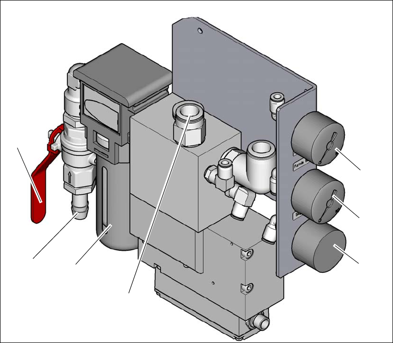
Fig. 4.4 - 2 Compressed air unit on the placement machine
Legend for fig.4.4 - 2
(1) Manometer for the placement machine component supply pressure
Target pressure: 0.51 ± 0.01 MPa, 5.1 ± 0.1 bar (display range 0 - 1.0 MPa, 0 - 10 bar)
(2) Manometer for supply pressure of gantries 1 to 2
Target pressure: 0.485 ± 0.01 MPa, 4.85 ± 0.1 bar (display range 0 - 1.0 MPa, 0 - 10 bar)
(3) Manometer for inlet pressure
Target pressure: 0.5 - 1.0 MPa, 5 - 10 bar (display range: 0 - 1.0 MPa, 0 - 10 bar)
(4) Compressed air supply for gantries
(5) Compressed air filter
(6) Compressed air connection
(7) Stop valve in the "OPEN" position
(6)
(1)
(2)
(3)
(5)
(7)
(4)