00198442-04_UM_TX-V2_EN.pdf - 第196页
4 Setting up and commissioning In struction manual SIPLACE TX 4.5 Setting up the placement mac hine From software version 714.0 12/2020 196 4.5.2.2 Removing the shipping brace on the Y a xis 4 Fig. 4.5 - 2 Shipping brace…
Instruction manual SIPLACE TX 4 Setting up and commissioning
From software version 714.0 12/2020 4.5 Setting up the placement machine
195
4.5.2 Removing the shipping braces from the gantries
The gantries are secured with a shipping brace in both the X and Y directions. After transportation
of the placement machine, remove the shipping braces.
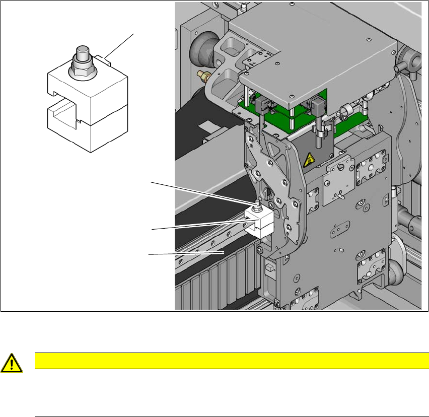
4.5.2.1 Removing the shipping brace on the X axis
4
Fig. 4.5 - 1 Shipping brace on the X axis
4
Loosen the screw (1) on the shipping brace (2) so that the shipping brace can be easily taken
off the linear guide.
4
CAUTION
Do not damage the scale!
The scale is located under the shipping brace (2).
Make sure that the scale (3) under the shipping brace is not damaged.
(1)
(3)
(2)
(4)
4 Setting up and commissioning Instruction manual SIPLACE TX
4.5 Setting up the placement machine From software version 714.0 12/2020
196
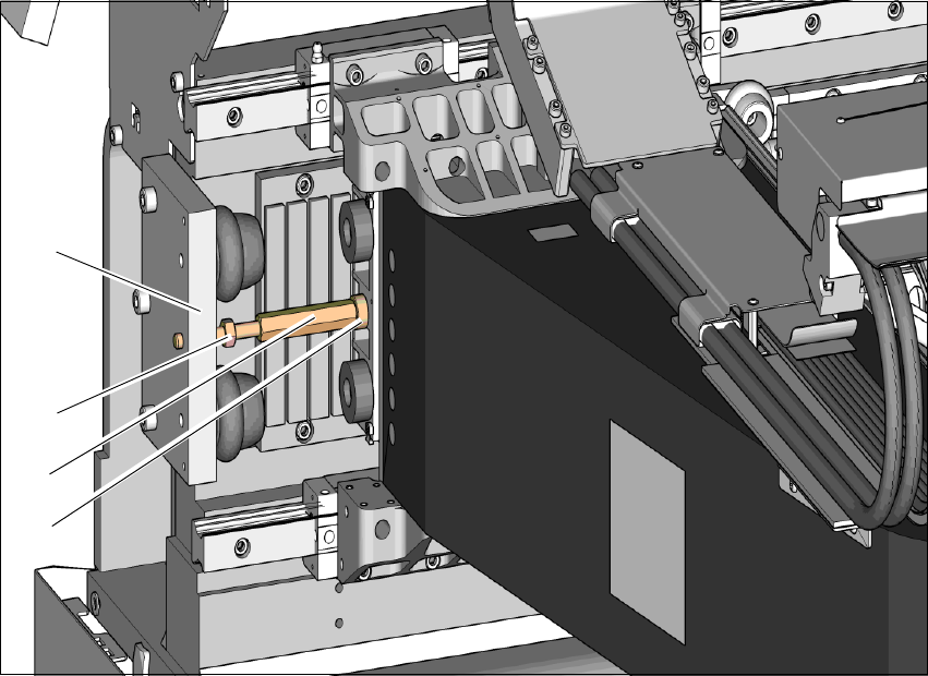
4.5.2.2 Removing the shipping brace on the Y axis
4
Fig. 4.5 - 2 Shipping brace on the Y axis
Loosen the counternut (2) holding the shipping brace (3) on the buffer plate (1) of the end
position stop.
Unscrew the counternut (2) 20 to 30 mm away from the buffer plate (1).
Use a size 13 fork wrench to loosen the shipping brace (3) from the gantry end (4) and un-
screw the shipping brace (3). Make sure you use the correct direction of rotation so that the
thread is not damaged.
Push the gantry to one side.
Unscrew the shipping brace completely from the buffer plate.
Keep the shipping brace safely for use later on. If the SIPLACE placement machine needs to
be transported, always fit the shipping braces again.
4.5.3 Fitting the shipping braces on the gantry axes
Before you transport the placement machine, always secure the X and Y axis of the gantry axes
with a shipping brace each. Fit these shipping braces.
(1)
(3)
(2)
(4)

Instruction manual SIPLACE TX 4 Setting up and commissioning
From software version 714.0 12/2020 4.5 Setting up the placement machine
197
4.5.3.1 Fitting the shipping brace on the X axis again
The shipping brace on the X axis fastens the head plate with the placement head on the gantry.
4
See also fig. 4.5 - 1, page 195).
Loosen the screw on the shipping brace so that the shipping brace can be easily fitted onto
the linear guide.
Push the placement head and the shipping brace up to the gantry base/input end.
Fit the shipping brace so that the placement head is fastened to the gantry base. The ridges
(item 4 in fig. 4.5 - 1
, page 195) on the shipping brace point towards the head.
Loosely tighten the screw on the shipping brace.
Press the placement head firmly towards the gantry base/input end again so that the place-
ment head has no play.
Tighten the screw on the shipping brace firmly.
4.5.3.2 Fitting the shipping brace on the Y axis again
The shipping brace on the Y axis fastens the gantry to the machine frame.
See also fig. 4.5 - 2
, page 196).
Unscrew the counternut 20 to 30 mm from the outer end of the long thread of the shipping
brace.
Push the gantry away from the buffer of the end position stop.
Screw the shipping brace with the long thread approx. 20 mm into the buffer plate (the thread
should protrude from the back by approx. 10 mm).
Carefully pull the gantry towards the short thread end of the shipping brace.
Screw the short thread into the hole on the gantry, as far as the stop.
Use a size 13 fork wrench to hand-tighten the shipping brace on the long hexagon.
Turn the counternut towards the buffer plate on the end position stop.
Hand tighten the counternut.
CAUTION
Do not damage the scale!
The scale is located under the shipping brace
Make sure that the scale (3) under the shipping brace is not damaged.