00198442-04_UM_TX-V2_EN.pdf - 第247页
Instruction manual SIPLACE TX 5 Tasks at the placement machine From software version 714.0 12/2020 5.9 Carrying out a sight chec k 247 5.9 Carrying out a sight check 5.9.1 Checking the X feeder modules 5 Fig. 5.9 - 1 Che…
5 Tasks at the placement machine Instruction manual SIPLACE TX
5.8 Shift changeover From software version 714.0 12/2020
246
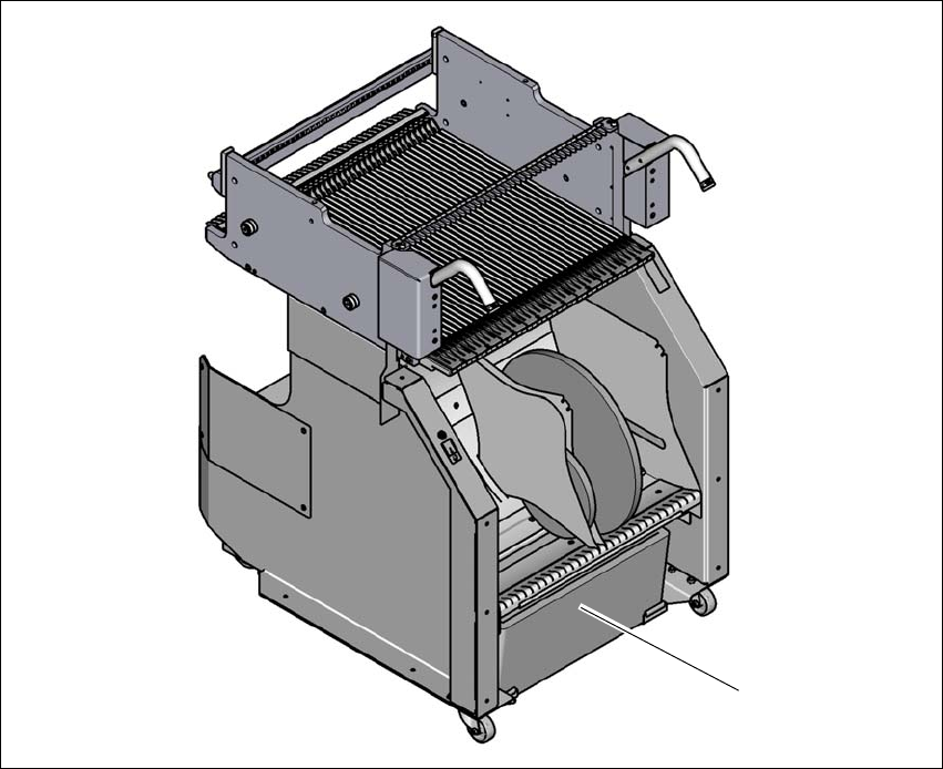
5.8.2 Safety instructions for emptying the waste tape container
5
Fig. 5.8 - 1 Safety instructions for emptying the waste tape container
(1) Waste tape container
The waste tape container must be pulled out of the component trolley for emptying. There is a risk
of catching your thumbs as you do so.
To avoid this risk, take hold of the underside of the waste tape container.
(1)
Instruction manual SIPLACE TX 5 Tasks at the placement machine
From software version 714.0 12/2020 5.9 Carrying out a sight check
247
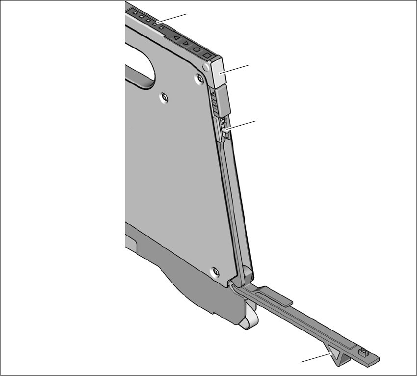
5.9 Carrying out a sight check
5.9.1 Checking the X feeder modules
5
Fig. 5.9 - 1 Checking the X feeder modules
(1) Flap
(2) Blade
(3) Status display
(4) LED display
5
Check to see whether the tape foil removal container for the X tape feeder module is full.
Open the flap (item 1). Pull out the cover foil and cut it off with the blade (item 2).
(1)
(2)
(3)
(4)

5 Tasks at the placement machine Instruction manual SIPLACE TX
5.9 Carrying out a sight check From software version 714.0 12/2020
248
5
Check the multicolor status display (item 3 in fig. 5.9 - 1, page 247).
– If it lights up green, the feeder module is on standby.
– If it lights up orange, it is signaling a warning. The LEDs will shine accordingly.
– If the status display lights up red, a malfunction has occurred. The LEDs will shine ac-
cordingly.
A list of the LED and status displays on the SmartFeeder operator panel is given in sec-
tion 5.11
, page 259. 5
If the status display is off, the cause may be as follows: 5
– The feeder module is not in the current setup.
– The feeder module is defective.
– The feeder module has been disabled (due to a drop in pressure, for example)
5.9.2 Splicing the tapes in good time
5
5.9.3 Checking the PCB supports
Check the position of the magnetic PCB supports on the lifting table:
– Make sure that the PCB supports do not collide with components on the underside of the
PCBs.
– In addition, make sure that the PCB supports do not collide with the PCB conveyor pan-
els.
– Only use PCB supports as described in section 6.8
, page 299.
CAUTION
Problems with cover foil withdrawal!
If the cover foil tears, this could lead to problems with the cover foil withdrawal.
PLEASE NOTE
Late splicing of tapes
Late splicing of tapes can lead to prolonged down times.
Splice the tapes early enough so that the feeder modules do not run out of compo-
nents.
PLEASE NOTE
Early splicing of tapes
Early splicing of tapes can have the following consequence: when the old tape is rolled
up onto the new reel, the new reel could become too full and the tape will slide off it and
get caught up. This will again result in pick-up errors and prolonged down times.