00198442-04_UM_TX-V2_EN.pdf - 第249页
Instruction manual SIPLACE TX 5 Tasks at the placement machine From software version 714.0 12/2020 5.10 Setting up the feeder mo dules 249 5.10 Setting up the feeder modules 5.10.1 Notes on handling feeder modules Feeder…
5 Tasks at the placement machine Instruction manual SIPLACE TX
5.9 Carrying out a sight check From software version 714.0 12/2020
248
5
Check the multicolor status display (item 3 in fig. 5.9 - 1, page 247).
– If it lights up green, the feeder module is on standby.
– If it lights up orange, it is signaling a warning. The LEDs will shine accordingly.
– If the status display lights up red, a malfunction has occurred. The LEDs will shine ac-
cordingly.
A list of the LED and status displays on the SmartFeeder operator panel is given in sec-
tion 5.11
, page 259. 5
If the status display is off, the cause may be as follows: 5
– The feeder module is not in the current setup.
– The feeder module is defective.
– The feeder module has been disabled (due to a drop in pressure, for example)
5.9.2 Splicing the tapes in good time
5
5.9.3 Checking the PCB supports
Check the position of the magnetic PCB supports on the lifting table:
– Make sure that the PCB supports do not collide with components on the underside of the
PCBs.
– In addition, make sure that the PCB supports do not collide with the PCB conveyor pan-
els.
– Only use PCB supports as described in section 6.8
, page 299.
CAUTION
Problems with cover foil withdrawal!
If the cover foil tears, this could lead to problems with the cover foil withdrawal.
PLEASE NOTE
Late splicing of tapes
Late splicing of tapes can lead to prolonged down times.
Splice the tapes early enough so that the feeder modules do not run out of compo-
nents.
PLEASE NOTE
Early splicing of tapes
Early splicing of tapes can have the following consequence: when the old tape is rolled
up onto the new reel, the new reel could become too full and the tape will slide off it and
get caught up. This will again result in pick-up errors and prolonged down times.
Instruction manual SIPLACE TX 5 Tasks at the placement machine
From software version 714.0 12/2020 5.10 Setting up the feeder modules
249
5.10 Setting up the feeder modules
5.10.1 Notes on handling feeder modules
Feeder modules are precision devices. You should therefore handle the feeder modules with care.
Avoid bumping feeder modules into obstacles.
Do not drop the feeder modules.
Always use suitable tools for preventive maintenance.
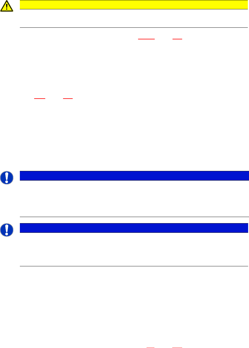
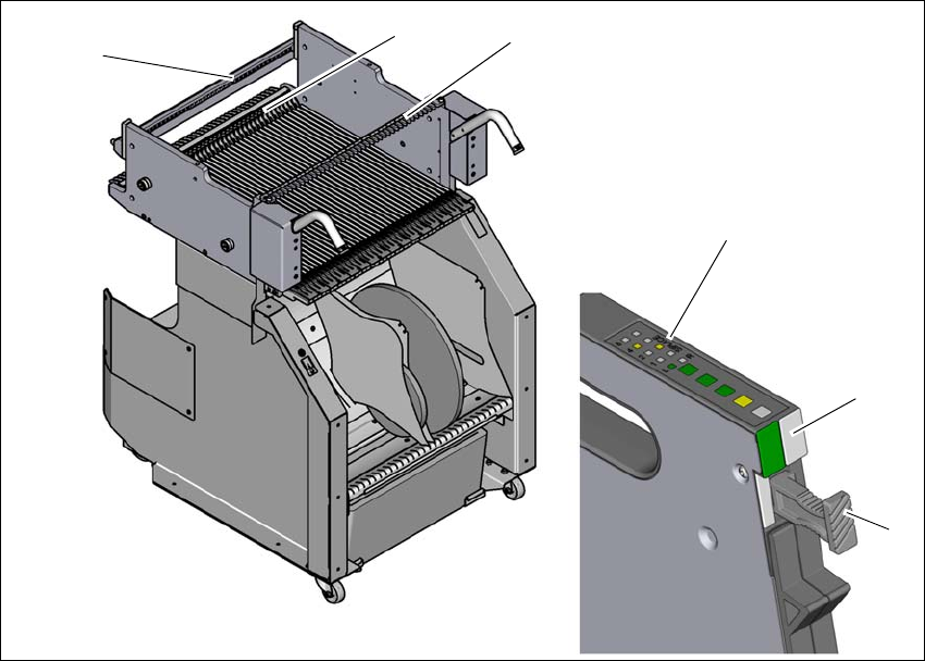
5.10.2 Removing X feeder modules from the changeover table
5
Fig. 5.10 - 1 Removing X feeder modules from the changeover table
(1) Removal handle
(2) Status display
(3) LED display
(4) Rail for checking height of feeder
(5) Latch for locking the feeder modules
(6) Centering rail
5
(2)
(1)
(4)
(5)
(6)
(3)

5 Tasks at the placement machine Instruction manual SIPLACE TX
5.10 Setting up the feeder modules From software version 714.0 12/2020
250
On standby, the status display (item 2 in fig. 5.10 - 1, page 249) lights up green if the X axis feeder
module is contained in the current setup. If the feeder module is not contained in the current setup,
the status display remains off.
The feeder module is locked in position in the changeover table by a latch, and cannot be pulled
out. The procedure for removing feeder modules from the changeover table is as follows:
Press the removal handle (item 1 in fig. 5.10 - 1, page 249). The removal handle jumps out
and the status display goes out.
Wait approximately 1 second until the lock (item 4 in fig. 5.10 - 1, page 249) releases the
feeder module.
Use the removal handle to pull the feeder module out of the changeover table. If you wait lon-
ger than 5 seconds, the feeder module will be locked once more. The status display will shine
red.
Engage the removal handle once more. If the feeder module is contained in the current setup,
the status display lights up green and the track number and increment will appear on the LCD
display once more.