00198442-04_UM_TX-V2_EN.pdf - 第72页
2 Operational safety Instruction manual SIPLACE TX 2.3 Classification of camera sys tems From software version 714.0 12/2020 72 2.3.2 Classification of the camera systems 2.3.2.1 Camera types with bright LEDs - risk gro …
Instruction manual SIPLACE TX 2 Operational safety
From software version 714.0 12/2020 2.3 Classification of camera systems
71
2.3 Classification of camera systems
2.3.1 Classification of placement machine
2
2.3.1.1 Laser classification
The following modules are assigned to risk class 2:
2
The ready-for-operation placement machine is assigned to risk class 2.
The risk classes are determined according to IEC 60825-1:2014.
Assembly Data
Component sensor on SpeedStar Maximum optical output power: < 1 mW
Wavelength: 635 nm
Component sensor on MultiStar Maximum optical output power: < 1 mW
Wavelength: 635 nm
Laser light barrier on PCB conveyor Maximum optical output power: < 1 mW
Wavelength: 650 nm

2 Operational safety Instruction manual SIPLACE TX
2.3 Classification of camera systems From software version 714.0 12/2020
72
2.3.2 Classification of the camera systems
2.3.2.1 Camera types with bright LEDs - risk group 1
The bright LEDs are fitted in the following cameras. These are classified as risk group 1, according
to IEC 62741:.
– Component camera type 23, 30, 41 and 45
– Stationary component camera type 25 and 33
– PCB camera, type 54
2
2.3.2.2 Camera types with blue LEDs - risk group 2
The ultra-bright blue LEDs are fitted in the following cameras. These are classified as risk group
2, according to IEC 62741:.
– Component camera, type 48
2
2
PLEASE NOTE
Risk group 1
Do not look into the beam of the ready-for-operation camera!
2
Risk group 2
The beam from cameras with ultra-bright blue LEDs can be a haz-
ard.
Do not look into the beam of the ready-for-operation camera!
Instruction manual SIPLACE TX 2 Operational safety
From software version 714.0 12/2020 2.4 Safety instructions for operation
73
2.4 Safety instructions for operation
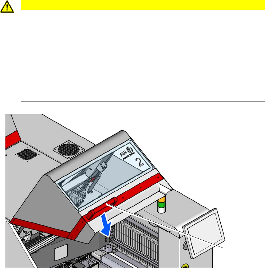
2.4.1 Safety instructions for closing the protective covers
The protective covers can be opened upwards in two positions (45° or 60°). To avoid risk of injury
when closing the protective covers on the placement machine, the operator must instruct the per-
sonnel concerned to always follow the instructions below when handling the protective covers.
2
2
Fig. 2.4 - 1 Safety instructions for closing the protective covers
(1) Handle
CAUTION
Risk of crushing hands!
Risk of crushing hands if the protective covers are not closed correctly.
Close the protective covers in accordance with the following instructions.
To open or close the protective covers, always take hold of these by the grab
handles (1).
When closing, do not reach into the gap between the protective cover and
panel.
When closing the protective cover, make sure that the area in which it is swiv-
eled is free of obstruction and that no other people are at risk of injury.
(1)