00198442-04_UM_TX-V2_EN.pdf - 第80页
2 Operational safety Instruction manual SIPLACE TX 2.5 Safety features From software version 714.0 12/2020 80 2.5 Safety features 2.5.1 Protective covers The travel range of the g antries is covered with two movable pr o…
Instruction manual SIPLACE TX 2 Operational safety
From software version 714.0 12/2020 2.4 Safety instructions for operation
79
2.4.9 Safety instructions for the TwinStar component cameras
2
2.4.10 Safety instructions for docking the component trolley in or out
2
2
2
2
2.4.11 Safety instructions for emptying the waste tape container
The waste tape container must be pulled out of the component trolley for emptying. There is a risk
of catching your thumbs as you do so. To prevent this, observe the safety instructions in section
5.8.2
, page 246.
WARNING
Risk of collisions!
When changing the placement head from a TwinStar/VHF to a SpeedStar, the SpeedStar
collides with the camera housing.
Dismantle the stationary component cameras of type 33, 55 x 45, and type 25, 16 x
16 for the TwinStar.
WARNING
Operation only with component trolley!
The placement machine may only be operated if there is a component trolley present
and docked at each location.
Fill any free locations with dummy feeder modules as described in
section 2.5.4
, page 92.
WARNING
DANGER OF CRUSHING!
Risk of crushing when docking and undocking the component trolley.
Always dock/undock the component trolley alone.
CAUTION
Risk of breaking handles!
Risk of breaking handles when transporting the component trolley.
When transporting the component trolley, do not lift it by its handles.
CAUTION
Risk of injuring limbs!
Risk of injuring limbs when docking and undocking.
When docking and undocking, make sure that there are no body limbs in the travel
area of the component trolley.
2 Operational safety Instruction manual SIPLACE TX
2.5 Safety features From software version 714.0 12/2020
80
2.5 Safety features
2.5.1 Protective covers
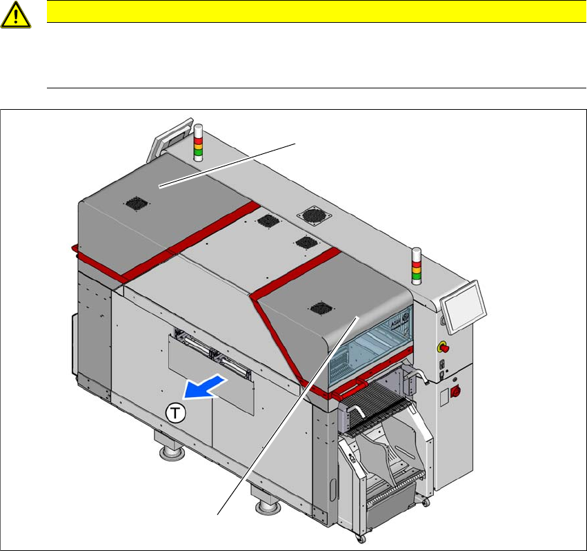
The travel range of the gantries is covered with two movable protective covers. The protective
hoods and covers serve as protective devices which prevent unauthorized access to the inside of
the placement machine.
2
2
Fig. 2.5 - 1 Protective covers
(1) Protective cover location 1
(2) Protective cover location 2
(T) Direction of travel
CAUTION
Risk of damage!
The protective covers and other covers could be damaged if too much force is exerted.
Do not stand on or climb up the protective covers and other covers.
(1)
(2)

Instruction manual SIPLACE TX 2 Operational safety
From software version 714.0 12/2020 2.5 Safety features
81
Function 2
If one of the protective covers is opened upwards, the power supply to the gantry axes will be im-
mediately interrupted. The gantry axes stop moving. The message "Close cover" is displayed on
the screen.
Close the protective covers and press the START button (item 2 in fig. 2.5 - 2), to continue
placement.