00198442-04_UM_TX-V2_EN.pdf - 第81页
Instruction manual SIPLACE TX 2 Operational safety From software version 714.0 12/2020 2.5 Safety features 81 Function 2 If one of the protective covers is o pened upwards, the power su pply t o the gantry axes will be i…
2 Operational safety Instruction manual SIPLACE TX
2.5 Safety features From software version 714.0 12/2020
80
2.5 Safety features
2.5.1 Protective covers
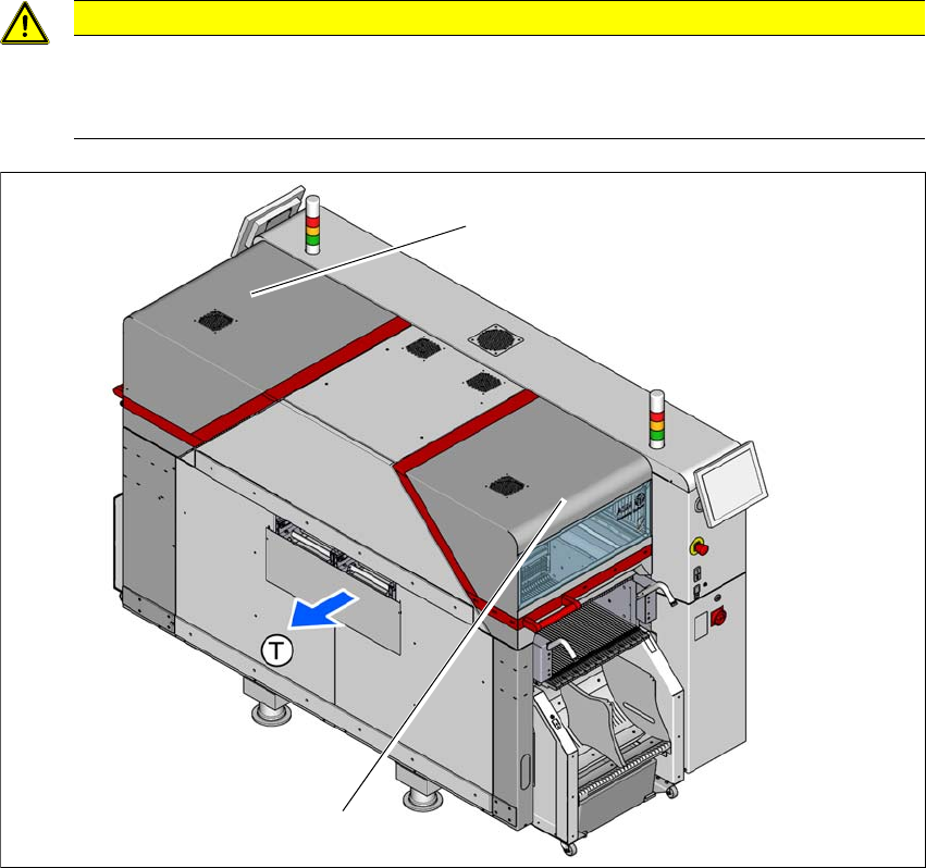
The travel range of the gantries is covered with two movable protective covers. The protective
hoods and covers serve as protective devices which prevent unauthorized access to the inside of
the placement machine.
2
2
Fig. 2.5 - 1 Protective covers
(1) Protective cover location 1
(2) Protective cover location 2
(T) Direction of travel
CAUTION
Risk of damage!
The protective covers and other covers could be damaged if too much force is exerted.
Do not stand on or climb up the protective covers and other covers.
(1)
(2)

Instruction manual SIPLACE TX 2 Operational safety
From software version 714.0 12/2020 2.5 Safety features
81
Function 2
If one of the protective covers is opened upwards, the power supply to the gantry axes will be im-
mediately interrupted. The gantry axes stop moving. The message "Close cover" is displayed on
the screen.
Close the protective covers and press the START button (item 2 in fig. 2.5 - 2), to continue
placement.
2 Operational safety Instruction manual SIPLACE TX
2.5 Safety features From software version 714.0 12/2020
82
2.5.2 Switches and buttons
2.5.2.1 Positions of switches and buttons
2
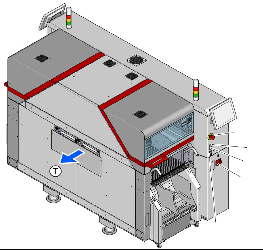
Fig. 2.5 - 2 Position of switches and buttons - PCB output end (location 2)
(1) EMERGENCY STOP button
(2) Start button (white)
(3) Stop button (black)
(4) Main switch
(5) Button for docking and undocking the component trolley at the respective location
(T) PCB transport direction
(3)
(1)
(4)
(2)
(5)