00198442-04_UM_TX-V2_EN.pdf - 第87页
Instruction manual SIPLACE TX 2 Operational safety From software version 714.0 12/2020 2.5 Safety features 87 Position switch location 1 and 2 (item 1 and 4 in fig. 2.5 - 4 , page 84 ) 2 This position switch checks wheth…

2 Operational safety Instruction manual SIPLACE TX
2.5 Safety features From software version 714.0 12/2020
86
Start button (item 1 in fig. 2.5 - 2, page 82 and item 1 in fig. 2.5 - 3, page 83) 2
After switching on the main power switch and starting the control program, you will be prompted
to press the start button in order to start the placement machine for placement jobs. The same
prompt will appear after you have opened the protective covers or pressed the EMERGENCY
STOP button and then want to recommence placement operations with the placement machine.
Press the start button for at least 200 ms, up to a maximum of 1500 ms, and then let go. The
placement machine will be switched on when you let go of the button and the protective cov-
ers will be mechanically held closed.
Stop button, black (item 2 in fig. 2.5 - 2, page 82 and item 2 in fig. 2.5 - 3, page 83) 2
These buttons are used to stop the placement machine. The mechanical closure on the protective
cover lock is released and the covers can be opened.
Component counter 2
The number of placed components (component counter) can be read on the station software. For
more information, refer to the Online Help.
EMERGENCY STOP button with forced locking (item 3 in fig. 2.5 - 2, page 82 and item 3 in fig.
2.5 - 3, page 83) 2
The EMERGENCY STOP button is red and latches in the ON position when pressed. When you
press the EMERGENCY STOP button, the switching contact of the EMERGENCY STOP circuit
opens and the safety cutoff (CBS) trips. The intermediate circuit voltage (300 VDC) for the gantry
axes and the intermediate circuit voltage (160 VDC) for the star axes is switched off. The servo
amplifiers for the DP and Z axes are still supplied with 42 VDC. The signaling contact of the
EMERGENCY STOP button opens and the message "EMERGENCY STOP pressed" appears on
the screen. The following modules are deactivated:
– PCB conveyor
– PCB clamping
– Width adjustment
– PCB stopper
– Compressed air supply for empty tape cutter
2
PLEASE NOTE
Placement will be interrupted and can then either be continued or canceled, once the
placement machine is working correctly again.
Instruction manual SIPLACE TX 2 Operational safety
From software version 714.0 12/2020 2.5 Safety features
87
Position switch location 1 and 2 (item 1 and 4 in fig. 2.5 - 4, page 84) 2
This position switch checks whether the protective covers are open or closed. The position
switches on the protective covers trigger the safety cutoff (lock) when a protective cover is
opened. Individual components are disabled or remain enabled (see fig. 2.5 - 6
, page 90 ). The
protective covers are mechanically locked during placement machine operation. The protective
covers can only be opened once the stop button has been pressed.
Protective cover switch for COT insert location 1 and 2 (item 2 and 3 in fig. 2.5 - 4, page 84) 2
This position switch checks whether the component trolley is docked onto the COT insert. The po-
sition switch on the COT insert triggers safety cutoff (lock) when one of the component trolleys is
undocked.
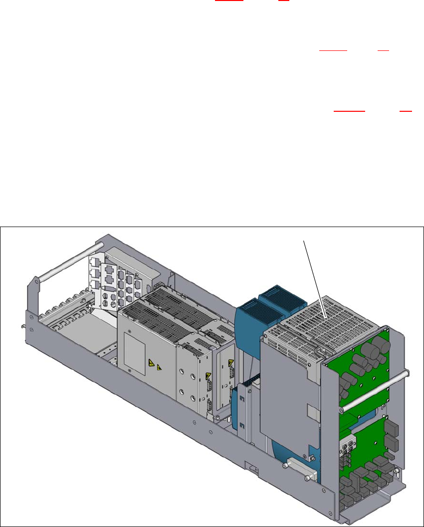
2.5.3 Safety cutoff (CSB)
2
2
Fig. 2.5 - 5 Position of the safety cutoff (CSB)
2
(1) Safety cutoff (CSB)
(1)

2 Operational safety Instruction manual SIPLACE TX
2.5 Safety features From software version 714.0 12/2020
88
Safety cutoff (CSB) (item 1 in fig. 2.5 - 5, page 87) 2
The safety cutoff (CSB) is located in the power supply unit. It is used to monitor the protective fea-
tures and checks for hazardous voltages or movements.
2
There are three conditions that must be fulfilled in order to activate the safety cutoff (CBS):
– All protective features and the EMERGENCY STOP buttons must be released.
– The start button must have been pressed.
– The "software release" or "Control ON" signal must be issued by the control software.
Service socket (only installed up to machine number TB070G) 2
The service socket is only installed in the SIPLACE TX up to machine number TB070G.
2
DANGER
Lethal voltages under the safety cutoff (CSB) cover!
Under the cover there are components which could still carry lethal voltages, even when
the placement machine is switched off and the mains plug has been disconnected. After
disconnecting the mains plug, wait 5 minutes until the capacitors have discharged.
Never open the covers.
Only ASM Assembly Systems GmbH&Co.KG service engineers or the machine
owner's service engineers, who have been trained by ASM, may perform work on the
power supply and the safety cutoff (CBS).
PLEASE NOTE
– The service socket can only be used in networks with a neutral conductor present
and connected.
– The service socket may only be used by trained service personnel.
– It is only to be used for the connection of service equipment which has the relevant
voltage range and for plugs which fit the service socket.
– The available voltage between L and N depends on the mains voltage supply at the
installation site.
– Please observe the applicable local regulations! If the service socket installed does
not comply with the applicable local regulations, it may not be used and must be
completely disabled!