00198442-04_UM_TX-V2_EN.pdf - 第92页
2 Operational safety Instruction manual SIPLACE TX 2.5 Safety features From software version 714.0 12/2020 92 2.5.4 Hand guards at the lo cations with dummy feeders 2 Fig. 2.5 - 7 Hand guard on the component trolley loca…
Instruction manual SIPLACE TX 2 Operational safety
From software version 714.0 12/2020 2.5 Safety features
91
2.5.3.2 Enabling the EMERGENCY STOP
If problems occur, the SIPLACE TX can be stopped by pressing the EMERGENCY STOP button.
An EMERGENCY STOP can be triggered by:
– Pressing one of the EMERGENCY STOP buttons on the placement machine
In these cases, the safety cutoffs are triggered and the power contactors will be switched off within
100 ms or 500 ms (STOP category 1, controlled shutdown with interruption of power supply during
downtime).
2.5.3.3 Resetting an EMERGENCY STOP
To reset an EMERGENCY STOP, unlock the EMERGENCY STOP button.
Find out the reason why the EMERGENCY STOP button triggered.
Remove the cause.
Unlock the relevant EMERGENCY STOP button.
2.5.3.4 Resetting the lock
Close the open protective cover.
2.5.3.5 Triggering the lock
Opening the protective cover.
2 Operational safety Instruction manual SIPLACE TX
2.5 Safety features From software version 714.0 12/2020
92
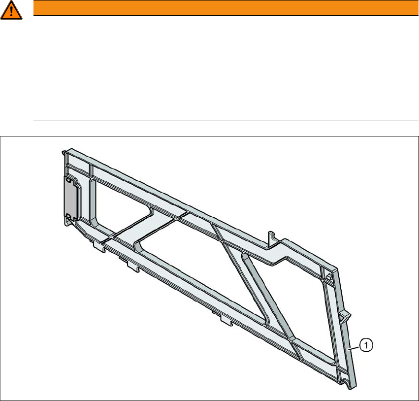
2.5.4 Hand guards at the locations with dummy feeders
2
Fig. 2.5 - 7 Hand guard on the component trolley locations
2
(1) Dummy feeder SIPLACE X, item no. 00141226-xx
WARNING
Operatio nal
Operational safety by occupying every second location!
The operational safety of the component trolley in the SIPLACE X-Series S is ensured if
at least every second free location is occupied with a feeder module or hand guard (dum-
my feeder).
Insert a hand guard (dummy feeder) at every second free location.
Even when configuring a holder for waffle pack trays, secure every second location
with a hand guard.
Instruction manual SIPLACE TX 2 Operational safety
From software version 714.0 12/2020 2.6 Residual voltages and discharge times
93
2.6 Residual voltages and discharge times
If the EMERGENCY STOP button is pressed or the placement machine is switched off, the 300
V- intermediate circuit voltage for the gantry axes and the 160 V- intermediate circuit voltage for
the star and Z axes will be reduced to harmless residual voltages within a very short time.
2
2.6.1 Energy state after switching off at the main power switch
2
2
DANGER
Dangerous voltage levels!
The placement machine is supplied with 3 x 380 V~ to 3 x 415 V ± 10 %, 50/60 Hz or op-
tionally with
3 x 200 V~ to 3 x 220 V~ ± 10 %; 50/60 Hz mains voltage. Due to the use of energy stor-
age capacitors, parts of the system may conduct hazardous voltages for a certain time
(approx. 5 minutes) even when the main switch has been switched off and the mains plug
has been disconnected.
Incorrect handling of this placement machine can therefore result in death or severe injury
or considerable damage to equipment.
Always follow the applicable accident prevention and DIN regulations (particularly EN
60204, part 1 or IEC 60204, part 1) and the applicable regulations in your own coun-
try.
The covers over the power supply unit may ONLY be opened by appropriately qual-
ified and trained personnel.
DANGER
Lethal voltages in the power supply unit!
The power supply unit has components (capacitors) which can still conduct potentially le-
thal voltages for approx. 5 minutes, even when the placement machine has been switched
off and the mains plug has been disconnected.
Wait at least 5 minutes before you perform work on the power supply unit.
Only ASM Assembly Systems GmbH&Co.KG service engineers or the machine
owner's service engineers, who have been trained by ASM, may perform work on the
power supply and the safety cutoff (CBS).
CAUTION
Data loss!
To avoid losing data, assess the following criteria before switching off your placement ma-
chine - (apart from in emergencies):
– Has the placement machine finished transmitting setup and panel data?
– Has the placement machine finished processing the PCB?
– Has the placement machine completed the run-up phase?