00192975-01.pdf - 第104页
Power supply S-20/S-23HM/F4/F5/F5H M/S-25HM/HS-50 Conversion Instruct ions 3.10 Converting the waf flepack changer from 3 x 230 VAC to 3 x 400 V AC 03/2001 E dition 104 Å Remove the three jumpe rs betwee n termin als 1U …
S-20/S-23HM/F4/F5/F5HM/S-25HM/HS-50 Conversion Instructions Power supply
03/2001 Edition 3 Converting the power supply on S-20/S-23HM/ S-25HM/F4/F5 and F5HM machines
103
3.10 Converting the wafflepack changer from 3 x 230 VAC to 3 x 400 VAC
RISK OF DEATH 3
Å To convert the wafflepack changer:
– switch off the placement machine,
– disconnect it from the power supply and
– secure it to prevent reclosing as described in section 1
, page 71
or 3
Å remove the main power plug for the wafflepack changer and the square plug for the safety loop
from the placement machine.
3.10.1 Converting transformer T1 from 3 x 230 VAC to 3 x 400 VAC
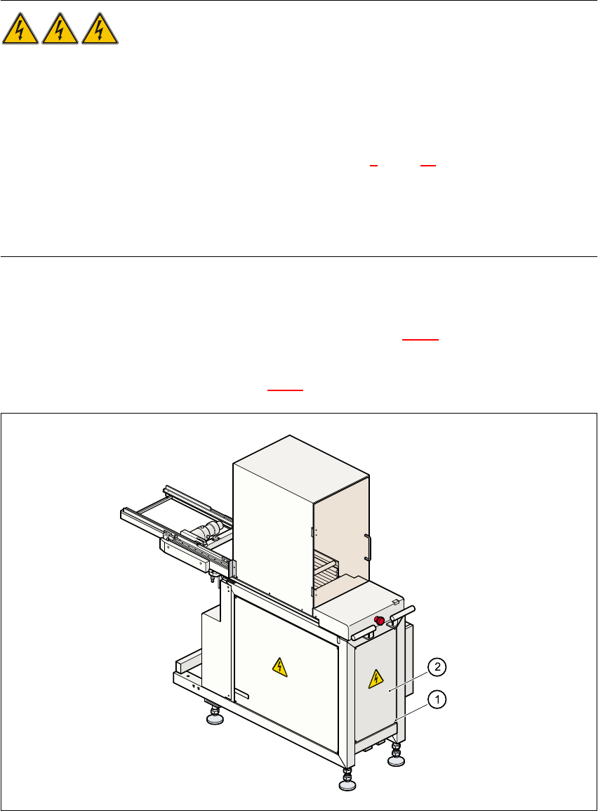
Å Loosen the four hexagon socket-head screws (item a in Fig. 3 - 15) on the rear panel of the
wafflepack changer.
Å Remove the cover plate (item s in Fig. 3 - 15).
Fig. 3 - 15 Wafflepack changer - accessing the power supply unit
Power supply S-20/S-23HM/F4/F5/F5HM/S-25HM/HS-50 Conversion Instructions
3.10 Converting the wafflepack changer from 3 x 230 VAC to 3 x 400 VAC 03/2001 Edition
104
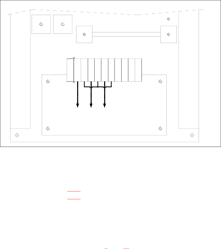
Å Remove the three jumpers between terminals 1U1 - 1W2, 1U2 - 1V1 and 1V2 - 1W2.
Fig. 3 - 16 Wafflepack changer, transformer T1, connection: 3 x 400 VAC
3
Å Place the two jumpers between the following terminals:
1U2 → 1V2 (see Fig. 3 - 16
)
1V2 → 1W2 (see Fig. 3 - 16
)
Å Finally, attach the cover plate to the rear panel of the wafflepack changer.
3.10.2 Carry out the safety check to DIN EN 60 204
Å When the conversion is complete, carry out a safety check to DIN EN 60 204.
Å Follow the procedure described in section 2, page 72 onwards.
3
Terminals
G1
G2
PE
T1
transformer
PE 1U11U2 1V1 1V21W11W2 65 65 65 N
3 x 400 VAC
S-20/S-23HM/F4/F5/F5HM/S-25HM/HS-50 Conversion Instructions Power supply
03/2001 Edition 3 Converting the power supply on S-20/S-23HM/ S-25HM/F4/F5 and F5HM machines
105
3.11 Circuit diagrams for S-20/S-23 HM/S-25 HM/F4/F5/F5 HM
=
G
e
p
r
.
N
o
r
m
B
e
a
r
b
.
U
r
s
p
r
.
E
r
s
.
f
.
E
r
s
.
d
.
N
a
m
e
S
I
E
M
E
N
S
A
G
+
P
E
L
2
L
2
3
1
7
A
F
C
D
2
L
1
E
D
L
1
5
4
6
N
L
3
L
3
5
P
E
3
7
8
C
B
A
N
N
5
F
6
8
1
4
B
W
a
W
a
T
e
k
0
1
.
0
1
.
0
1
.
1
4
.
1
0
.
9
8
1
4
.
1
0
.
9
8
1
4
.
1
0
.
1
9
9
8
B
e
r
g
e
r
#
0
0
1
1
7
1
8
5
-
0
1
0
1
0
1
L
D
3
1
0
.
0
3
.
9
9
E
X
2
0
6
2
P
E
P
L
E
A
1
E
2
3
1
2
g
n
y
e
B
R
3
2
,
5
m
m
2
B
R
4
g
n
y
e
P
o
w
e
r
s
u
p
p
l
y
u
n
i
t
(
c
o
n
t
r
o
l
u
n
i
t
)
2
,
5
m
m
2
1
5
0
V
/
6
0
H
z
r
d
2
,
5
m
m
T
e
r
m
i
n
a
l
p
a
n
e
l
(
r
i
g
h
t
-
h
a
n
d
s
i
d
e
)
S
e
c
t
i
o
n
a
)
:
D
a
t
e
S
h
e
e
t
D
a
t
e
M
o
d
i
f
i
c
a
t
i
o
n
I
s
s
u
e
S
h
.
f
o
r
S
I
P
L
A
C
E
8
0
S
2
0
/
S
2
3
/
F
4
/
F
5
S
I
P
L
A
C
E
8
0
S
2
0
/
S
2
3
/
F
4
/
F
5
S
M
D
P
l
a
c
e
m
e
n
t
S
y
s
t
e
m
F
u
n
c
t
i
o
n
s
t
a
t
u
s
P
r
o
d
u
c
t
s
t
a
t
u
s
D
o
c
u
m
e
n
t
s
t
a
t
u
s
1
1
0
/
2
0
8
V
C
o
n
v
e
r
s
i
o
n
K
i
t
P
l
e
a
s
e
n
o
t
e
T
N
-
C
s
y
s
t
e
m
I
n
a
f
o
u
r
-
w
i
r
e
T
N
-
C
s
y
s
t
e
m
,
t
h
e
n
e
u
t
r
a
l
a
n
d
P
E
c
o
n
d
u
c
t
o
r
f
u
n
c
t
i
o
n
s
m
u
s
t
b
e
c
o
m
b
i
n
e
d
i
n
a
s
i
n
g
l
e
c
o
n
d
u
c
t
o
r
t
h
e
P
E
N
c
o
n
d
u
c
t
o
r
t
h
r
o
u
g
h
o
u
t
t
h
e
e
n
t
i
r
e
s
y
s
t
e
m
(
j
u
m
p
e
r
s
B
R
3
/
B
R
4
)
.
P
l
e
a
s
e
n
o
t
e
T
N
-
S
s
y
s
t
e
m
J
u
m
p
e
r
s
B
R
3
/
B
R
4
m
u
s
t
n
o
t
b
e
u
s
e
d
i
n
a
f
i
v
e
-
w
i
r
e
T
N
-
S
s
y
s
t
e
m
.
(
T
h
e
n
e
u
t
r
a
l
a
n
d
P
E
c
o
n
d
u
c
t
o
r
s
a
r
e
k
e
p
t
s
e
p
a
r
a
t
e
t
h
r
o
u
g
h
o
u
t
t
h
e
s
y
s
t
e
m
)
.