00192975-01.pdf - 第115页
S-20/S-23HM/F4/F5/F 5HM/S-25HM/HS- 50 Conversion Instructions Power supply 03/2001 Edition 4 Converting the power supply unit on HS-50 placement m achines 115 4 Å Che ck the ov ercurre nt and sho rt-circ uit curre nt tri…
Power supply S-20/S-23HM/F4/F5/F5HM/S-25HM/HS-50 Conversion Instructions
4.4 Converting the power supply from 3 x 400 VAC to 3 x 204 V ~ 03/2001 Edition
114
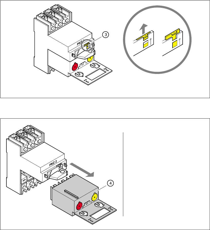
Fig. 4 - 5 Releasing the yellow locking tab
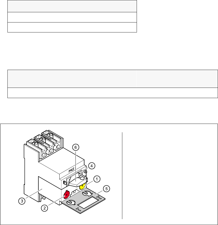
Fig. 4 - 6 Removing the motor protection trip block MS1A
4.4.2.2 Inserting the motor protection trip block
Å Check the type of motor protection trip block before you insert it. The type depends on the
operating voltage.
Use the screwdriver to push up the yellow locking tab (3)
Pull out the motor protection
trip block (4)
S-20/S-23HM/F4/F5/F5HM/S-25HM/HS-50 Conversion Instructions Power supply
03/2001 Edition 4 Converting the power supply unit on HS-50 placement machines
115
4
Å Check the overcurrent and short-circuit current trip threshold settings.
Fig. 4 - 7 Checking the overcurrent and short-circuit current trip thresholds
Å Insert the motor protection trip block a.
Å Push the yellow locking tab f down.
Å Close the gray protective flap g.
Å Turn the rotary switch h clockwise as far as the stop.
Main power voltages Type
3x204 VAC ± 5% ZM-32-PKZ2
3x230 VAC ± 5% ZM-32-PKZ2
Tab. 4 - 2 Motor protection trip block for 3x204 VAC, 3x230 VAC
Motor protection trip
block
Yellow dial (1) for setting the
overcurrent trip threshold
Red dial (2) for setting the short-
circuit current trip threshold
ZM-32-PKZ2 24 A 375 A
Tab. 4 - 3 Overcurrent and short-circuit current trip thresholds
Check the overcurrent trip
threshold (yellow dial a)
Check the short-circuit
current trip threshold
(red dial s)

Power supply S-20/S-23HM/F4/F5/F5HM/S-25HM/HS-50 Conversion Instructions
4.4 Converting the power supply from 3 x 400 VAC to 3 x 204 V ~ 03/2001 Edition
116
4.4.3 Replacing the socket with earthing contact
See item BU1 in Fig. 4 - 2, page 112.
Å Remove the cover flap over the socket with earthing contact.
Å Remove the socket insert.
Å Detach the wires.
Å Attach the wires to the US standard socket.
Å In particular, make sure that the yellow-green PE conductor is correctly connected to the
earthing contact (PE).
Å Fix the socket insert and cover flap in place.
4.4.4 Replacing the main power cable
The main power cable is connected to the U, V, W, N and PE terminals on terminal strip X1 (see
item X1 in Fig 4 - 2
, page 112).
Å Detach the wires of the main power cable from the U, V, W, N and PE terminals.
Å Detach the cable clamp from the cable holder.
Å Pull the cable out of the cable holder.
Å Push the main power cable (6 mm²) through the cable holder as far as the terminals on X1.
PLEASE NOTE: 4
Make sure that the cable bending radius is sufficient to prevent the wires being bent. 4
Å Connect the main power cable to the terminals on X1:
Wire 1 to U on X1,
Wire 2 to V on X1,
Wire 3 to W on X1,
Wire 4 to N on X1 and
Wire 1 to PE on X1.
(See circuit diagram 00119085-010101LD4, page 2)
Å Tighten the cable clamp.