00192975-01.pdf - 第121页
S-20/S-23HM/F4/F5/F 5HM/S-25HM/HS- 50 Conversion Instructions Power supply 03/2001 Edition 4 Converting the power supply unit on HS-50 placement m achines 121 Fig. 4 - 12 Power supply unit - front view MS1 Motor circui t…
Power supply S-20/S-23HM/F4/F5/F5HM/S-25HM/HS-50 Conversion Instructions
4.5 Converting the power supply from 3 x 204 VAC to 3 x 400 V ~ 03/2001 Edition
120
4.5.1 Removing the power supply unit
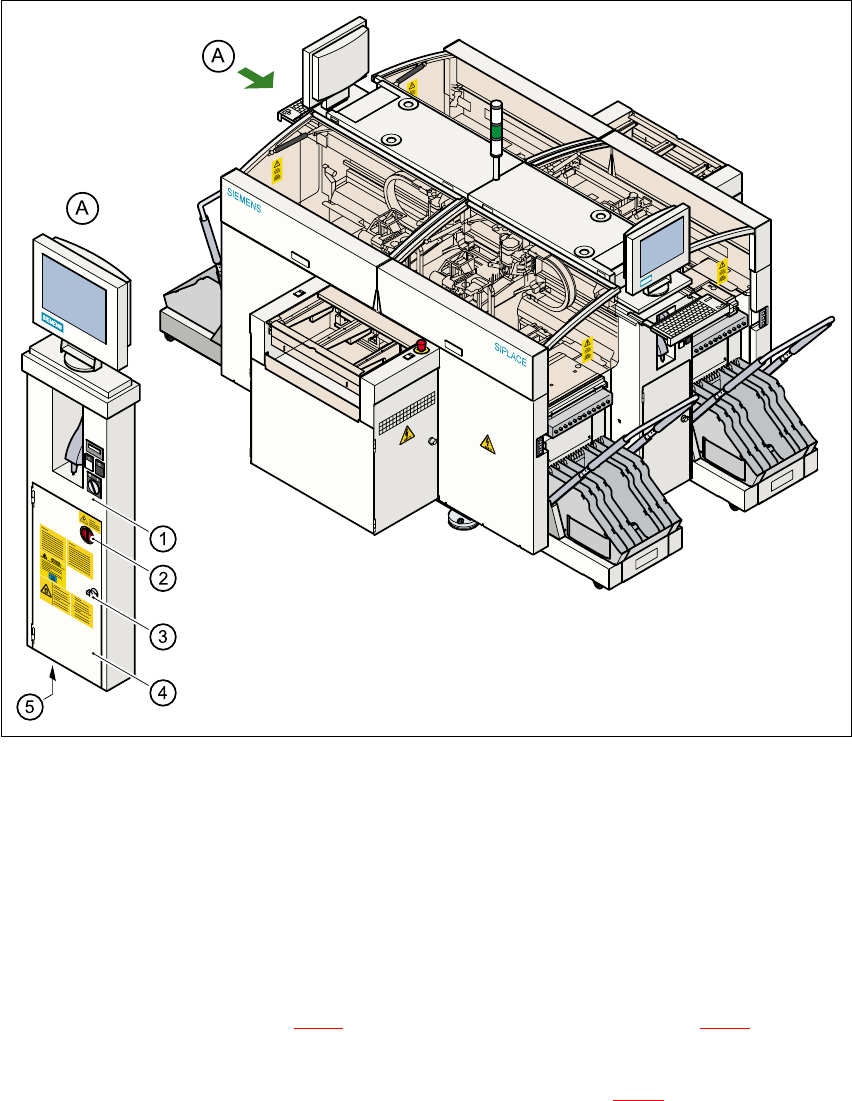
Fig. 4 - 11 Accessing the power supply unit
a 2SHUDWRUSDQHOOHIWKDQGVLGH
s 0DLQVZLWFK
d 'RRUORFN
f 3URWHFWLYHGRRUVWRSRZHUVXSSO\XQLW
g +ROHIRUSRZHUFDEOH
Å Open the lock (item d in Fig. 4 - 11) on the protective doors (item f in Fig. 4 - 11 using the
two-way key.
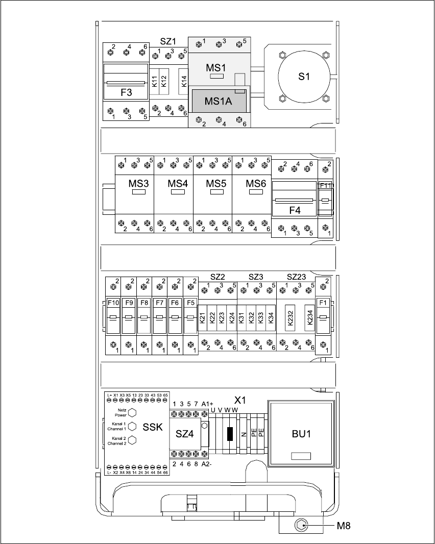
Å Use the Allen key to loosen the M8 locking screw (item M8 in Fig. 4 - 12) on the lower front
panel.
Å Pull the power supply unit out as far as the stop.
S-20/S-23HM/F4/F5/F5HM/S-25HM/HS-50 Conversion Instructions Power supply
03/2001 Edition 4 Converting the power supply unit on HS-50 placement machines
121
Fig. 4 - 12 Power supply unit - front view
MS1 Motor circuit-breaker
MS1A Motor protection trip block
X1 Terminal strip for the main power cable
BU1 Service socket
M8 Locking screw for power supply unit
Power supply S-20/S-23HM/F4/F5/F5HM/S-25HM/HS-50 Conversion Instructions
4.5 Converting the power supply from 3 x 204 VAC to 3 x 400 V ~ 03/2001 Edition
122
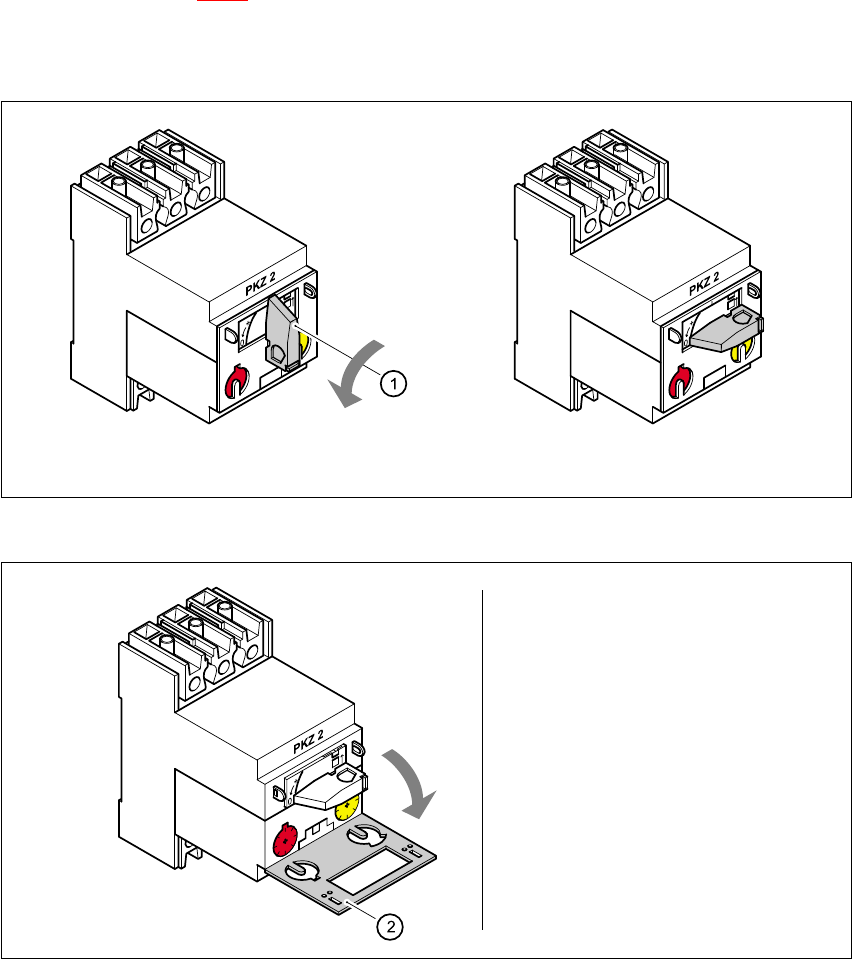
4.5.2 Replacing the motor protection trip block
The ZM-16-PKZ2 motor protection trip block, article number 00342495-01, must be used for
3x380 VAC, 3x400 VAC and 3x415 VAC supply voltages. The position of the motor protection trip
block is shown in Fig. 4 - 12
, item MS1A.
4.5.2.1 Removing the motor protection trip block
4
Fig. 4 - 13 Removing the motor protection trip block MS1A
4
Fig. 4 - 14 Lifting the protective flap
Turn the switch (1) counter-clockwise to the "0" position
Lift the
protective flap (2)