00192975-01.pdf - 第79页
S-20/S-23HM/F4/F5/F 5HM/S-25HM/HS- 50 Conversion Instructions Power supply 03/2001 Edition 2 Sa fety che ck t o DI N E N 6 0 204 79 2.5.3 Carrying out t he PE conductor test Å Me asure the im pedanc e of the PE conduc to…
Power supply S-20/S-23HM/F4/F5/F5HM/S-25HM/HS-50 Conversion Instructions
2.5 PE conductor test 03/2001 Edition
78
Å Enter the measured value into the test report.
If the measured value is < 100 mA, the machine has passed the high-voltage test and can be
released. If the measured value is greater, the error must be eliminated. and the test repeated.
2.5 PE conductor test
2.5.1 Permissible impedance values for the PE conductors
The PE test is used to test the continuity of the PE conductor system by means of a loop
impedance measurement to IEC 60364-6-61, 612.6.3. 2
PLEASE NOTE:
All the electrical connections must be fully installed on the machine, including those for the power
supply. 2
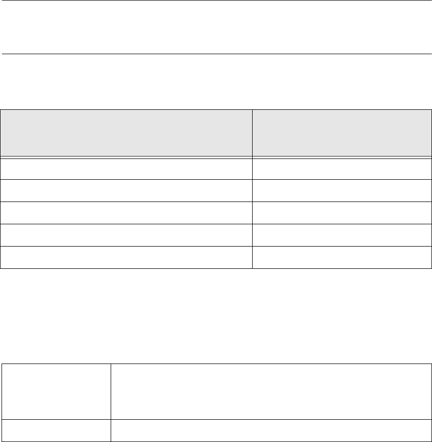
The impedances measured between the PE terminal and the test points must not exceed the
values shown in the following table. 2
2
2.5.2 PE conductor testers
Smallest effective PE conductor cross-section in
branch to be tested
[mm²]
Maximum permissible impedance
[Ohm]
1.0 0.33
1.5 0.26
2.5 0.19
4.0 0.14
> 6.0 0.1
Tab. 2 - 3 Permissible impedance values for different PE conductor cross-sections
Available testers
• ELECTROTECHNICAL LABORATORY, KORNTAL RD28K safety tester
• GOSSEN-METRAWATT 204P
• METRAMACHINE 204 (compete system for tests to VDE0113) consisting
of Profikit 204, Profitest 204 HP, Signal 204, Leadex 204, Caddy 204
Test duration 10 seconds
Tab. 2 - 4 PE conductor testers

S-20/S-23HM/F4/F5/F5HM/S-25HM/HS-50 Conversion Instructions Power supply
03/2001 Edition 2 Safety check to DIN EN 60 204
79
2.5.3 Carrying out the PE conductor test
Å Measure the impedance of the PE conductor (yellow-green). Measure at the point furthest from
the PE conductor infeed point. The test duration should be at least 10 seconds.
Å Document the measured values in the test report.
Å Compare the measured values against those in table 2 - 1 on page 75.
Å Record whether the test was passed or not.
Å The machine may be released if the test is passed.
Å If the test is not passed, the error must be eliminated and the test repeated.

Power supply S-20/S-23HM/F4/F5/F5HM/S-25HM/HS-50 Conversion Instructions
3.1 Versions of the affected power supply units 03/2001 Edition
80
3 Converting the power supply on S-20/S-23HM/
S-25HM/F
4
/F
5
and F5HM machines
3.1 Versions of the affected power supply units
This section describes how to convert the power supply units on SIPLACE S-20/
S-23HM/S-25HM/F4/F5 and F5HM placement machines, the changeover table and wafflepack
changer. This will allow the power supply units to be adapted to the supply networks in individual
countries. 3
These instructions apply to machines with the following power supply unit releases: 3
– S-20/F
4
/F
5
with 00321086 power supply unit, release 05 or later
– S-23HM/S-25HM/F5HM with 00336812 power supply unit, release 02 or later
PLEASE NOTE: 3
For S-20/F
4
-/F
5
machines with the 00321086 power supply unit, release 04, the conversion is
described in the instructions for S-15/F3 and G machines. 3
3.2 Modules to be converted
The following table lists those modules that have to be converted in order to adapt them to the
power supply network.
Machine Module Sub-module Ratings
S-20/F
4
/F
5
00321086-05
power supply unit
Transformer T1
3 x 400 VAC ± 5%/50 Hz
3 x 208 VAC ± 5%/60 Hz
Transformer T2
230 VAC ± 5 %/50 Hz
120 VAC ± 5 %/60 Hz
ESB S-20 A1 inrush
current limiter
3 x 400 VAC/50 Hz
3 x 208 VAC/60 Hz
S-23HM/
S-25HM
F5HM
Power supply
00336812-02
Transformer T1
3 x 400 VAC ± 5%/50 Hz
3 x 208 VAC ± 5%/60 Hz
Transformer T2
230 VAC ± 5 %/50 Hz
120 VAC ± 5 %/60 Hz
ESB S-20 A1 inrush
current limiter
3 x 400 VAC/50 Hz
3 x 208 VAC/60 Hz
Tab. 3 - 1 Modules to be converted