00192975-01.pdf - 第83页
S-20/S-23HM/F4/F5/F 5HM/S-25HM/HS- 50 Conversion Instructions Power supply 03/2001 Edition 3 Converting the power supply on S-20/S-23HM/ S-25HM/F4/F5 and F5HM machines 83 3.5.1 Removing the power sup ply unit Å Lo osen t…

Power supply S-20/S-23HM/F4/F5/F5HM/S-25HM/HS-50 Conversion Instructions
3.5 Converting placement machines from 3x400V~ to 3x208V~ 03/2001 Edition
82
(jumpers BR3 and BR4 for the right-hand terminal block for 4-conductor power connection, PE
and N conductors are bridged)
– 1.5 mm² single wire, black (jumper for WPC ∆ configuration)
– Circuit diagram, 110/208 V conversion kit for Siplace S-20/S-23HM/F
4
/F
5
,
Drawing no. 00117185-010101LD3, 3 pages (see 3.11
from page 105)
– Conversion instructions, power supply unit for Siplace S-20/S-23HM/S-25HM/F
4
/F
5
/F5HM/
HS-50, article number 00191498-01, 03/2001 issue, German and English
3.5 Converting placement machines from 3x400V~ to 3x208V~
PLEASE NOTE: 3
Uncouple the two changeover tables before switching off the machine.
The wafflepack changer can remain coupled to the machine during conversion. 3
RISK OF DEATH 3
Å Disconnect the machine correctly as described in section 1, page 71.
Å Disconnect the machine from the main power supply.
Å Take suitable action to ensure that the machine cannot be connected to the power supply
during the conversion work.
Å Put up warning signs to indicate that work is being carried out on the electrical system.
S-20/S-23HM/F4/F5/F5HM/S-25HM/HS-50 Conversion Instructions Power supply
03/2001 Edition 3 Converting the power supply on S-20/S-23HM/ S-25HM/F4/F5 and F5HM machines
83
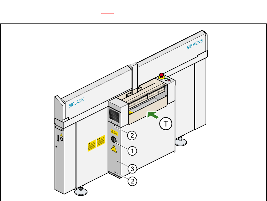
3.5.1 Removing the power supply unit
Å Loosen the two hexagon socket head screws (item 2 in Fig. 3 - 1).
Å Remove the cover (item 3 in Fig. 3 - 1).
Fig. 3 - 1 Removing the cover over the power supply unit
a 0DLQVZLWFK
s +H[DJRQVRFNHWKHDGVFUHZ[
d &RYHU
(T) PCB transport direction 3
3
Å Loosen the hexagon socket-head screw at the bottom of the power supply unit.
Å Take hold of the handle and remove the power supply unit from the housing.
The terminals on transformers T1 and T2 and the inrush current limiter can now be accessed
for rewiring.
Power supply S-20/S-23HM/F4/F5/F5HM/S-25HM/HS-50 Conversion Instructions
3.5 Converting placement machines from 3x400V~ to 3x208V~ 03/2001 Edition
84
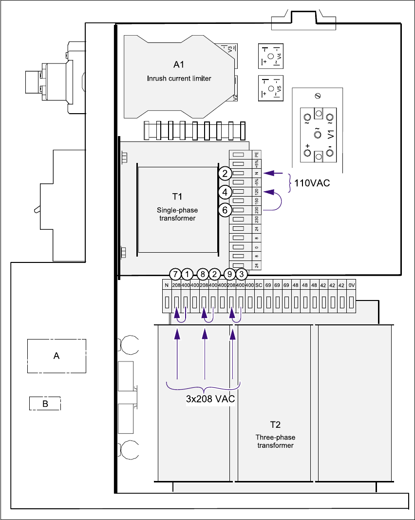
Fig. 3 - 2 Terminals on transformers T1 and T2 and the inrush current limiter
(T1) Single phase transformer T1 s - h 230 VAC
s - f 110 VAC
(T2) Three-phase transformer T2 a, s, d 3 x 400 VAC
j, k, l 3 x 208 VAC
(A1) Inrush current limiter 3