00192975-01.pdf - 第98页
Power supply S-20/S-23HM/F4/F5/F5H M/S-25HM/HS-50 Conversion Instruct ions 3.8 Converting placement machines from 3 x 208 V ~ to 3 x 400 V ~ 03/2001 Edition 98 3.8.6 4 or 5-wire connecti on for the power supply The conn …
S-20/S-23HM/F4/F5/F5HM/S-25HM/HS-50 Conversion Instructions Power supply
03/2001 Edition 3 Converting the power supply on S-20/S-23HM/ S-25HM/F4/F5 and F5HM machines
97
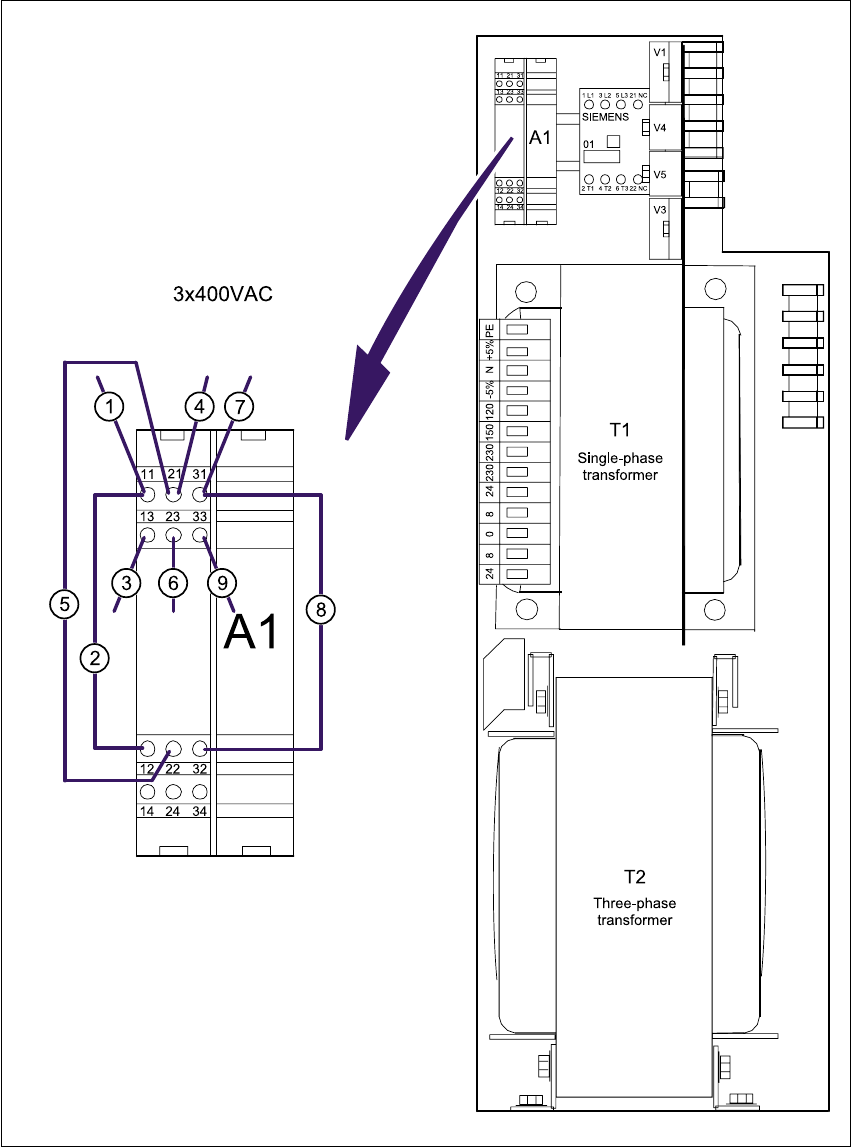
Fig. 3 - 11 Front panel of the power supply unit - connecting the inrush current limiter (003429988-01)
a - l Numbers of the connecting wires
A1 Inrush current limiter 3

Power supply S-20/S-23HM/F4/F5/F5HM/S-25HM/HS-50 Conversion Instructions
3.8 Converting placement machines from 3x208V~ to 3x400V~ 03/2001 Edition
98
3.8.6 4 or 5-wire connection for the power supply
The connections are produced using either 4 or 5 wires, according to the electricity company’s
requirements. 3
4-wire connection 3
In the 4-wire connection, the neutral conductor (NE) and protective earth (PE) are combined to
form a single PEN wire. 3
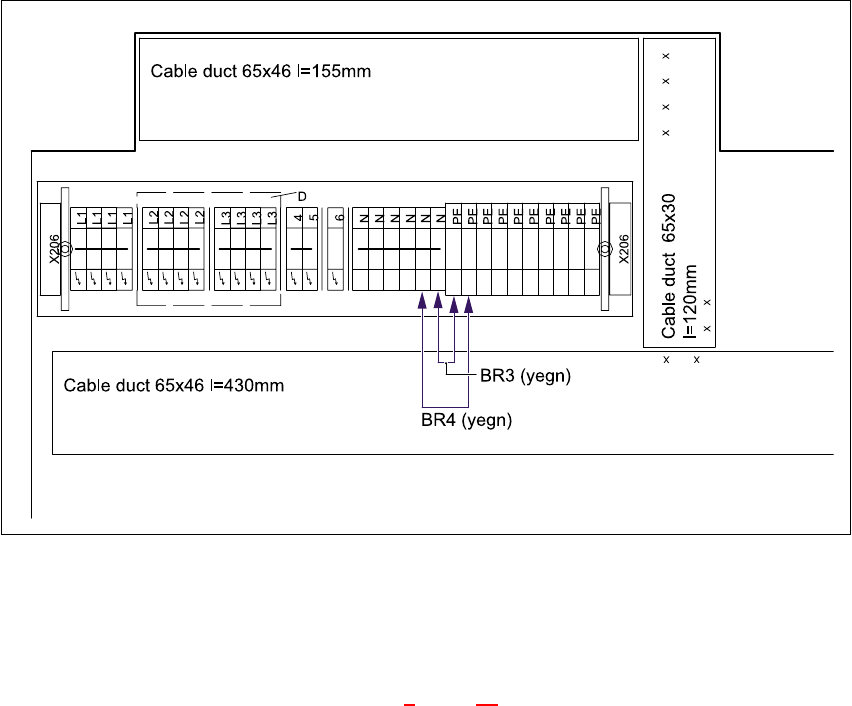
Å Insert the yellow-green wires BR3 and BR4 between the N and PE terminals in the right-hand
terminal block on terminal strip X206 (see Fig. 3 - 12
).
5-wire connection 3
In the 5-wire connection, the neutral conductor (NE) and protective earth (PE) consist of separate
wires. 3
Å Remove the yellow-green wires BR3 and BR4 from between the N and PE terminals in the
right-hand terminal block on terminal strip X206 (see Fig. 3 - 12
).
Machine Terminal block
Terminal strip X206
Jumpers BR3 and BR4 between PE and N
4-wire connection 5-wire connection
S-20/F4/F5 00321510-xx Yes No
S-23HM/S-25HM/F5HM 00337342-xx Yes No
Tab. 3 - 4 Terminal blocks, right-hand side
S-20/S-23HM/F4/F5/F5HM/S-25HM/HS-50 Conversion Instructions Power supply
03/2001 Edition 3 Converting the power supply on S-20/S-23HM/ S-25HM/F4/F5 and F5HM machines
99
Fig. 3 - 12 Terminal block, right-hand side, terminal strip X206
3.8.7 Carry out the safety check to DIN EN 60 204
Å When the conversion is complete, carry out a safety check to DIN EN 60 204.
Å Follow the procedure described in section 2, page 72 onwards.
3
3