00191369-01.pdf - 第107页
User’s Manual SIPLACE HS-50 3 Introduction and Basic Concepts Software Version SR.501.xx Edition 01/99 3.2 Principles of the Graphic User Interface 105 0HDQLQJRI2 WKHU,FRQV DQG0DUNLQJV If a trac k error , mach in…
3 Introduction and Basic Concepts User’s Manual SIPLACE HS-50
3.2 Principles of the Graphic User Interface Software Version SR.501.xx Edition 01/99
104
Å Check the box "Abort processing PCB" if the PCB is to be transported to the output
conveyor without further processing.
Å Check the box "PCB not to be assembled in PA2" if the PCB is to be processed on
processing conveyor 1 and is then to be transported to the output conveyor without being
processed on processing conveyor 2.
Å Click the $FFHSW button.
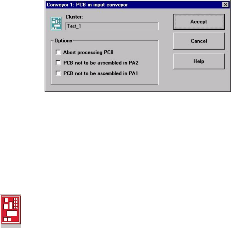
If the PCB is located on the input conveyor, the following dialog box is opened.
Å Check the box "Abort processing PCB" if the PCB is to be transported to the output
conveyor without further processing.
Å Check the box "PCB not to be assembled in PA2" if the PCB is to be processed on
processing conveyor 1 only and is then to be transported to the output conveyor without
being processed on processing conveyor 2.
Å Check the box "PCB not to be assembled in PA1" if the PCB is to be transported through
processing conveyor 1 without being processed and is then to be processed on processing
conveyor 2.
Å Click the $FFHSW button.
3URFHVVLQJRI3&%DERUWHG
If processing of the PCB has been aborted by a click on the PCB icon (see example above),
the color of the PCB icon changes to red.
The icon is also displayed in red if a PCB is manually placed on processing conveyor 1 or 2.
The PCB is not recognized by the system and is transported to the output conveyor.
User’s Manual SIPLACE HS-50 3 Introduction and Basic Concepts
Software Version SR.501.xx Edition 01/99 3.2 Principles of the Graphic User Interface
105
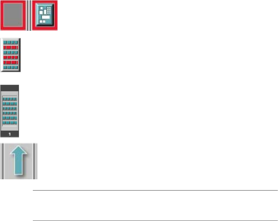
0HDQLQJRI2WKHU,FRQVDQG0DUNLQJV
If a track error, machine error or conveyor error occurs, then the corresponding graphic is
highlighted in red (see examples below).
Examples: If an error occurs in a processing area, then this is displayed with a red
border.
You can abort processing of the PCB which is located in this area by clicking the
PCB icon.
If a conveyor error occurs during transport, this is indicated by the presence of red
bars on the left and right.
If a track error occurs (e.g. missing components), then individual parts of the
graphic which correspond to the layout of the current feeder location are
displayed
against a red background. In addition, the graphic is displayed with a contour.
If you click this graphic, you can use the corresponding function to "refill" the
location (see Chapter 4).
0DFKLQHHUURU
&RPSRQHQWVPLVVLQJDWIHHGHUORFDWLRQ
)HHGHUORFDWLRQIXOO
&RQYH\RUVHWWR7UDQVSRUWWKURXJK
NOTE
This means that the "Process PCB" function is deactivated in the machine options.
The PCBs are passed through the entire transport process without being processed.
3 Introduction and Basic Concepts User’s Manual SIPLACE HS-50
3.2 Principles of the Graphic User Interface Software Version SR.501.xx Edition 01/99
106
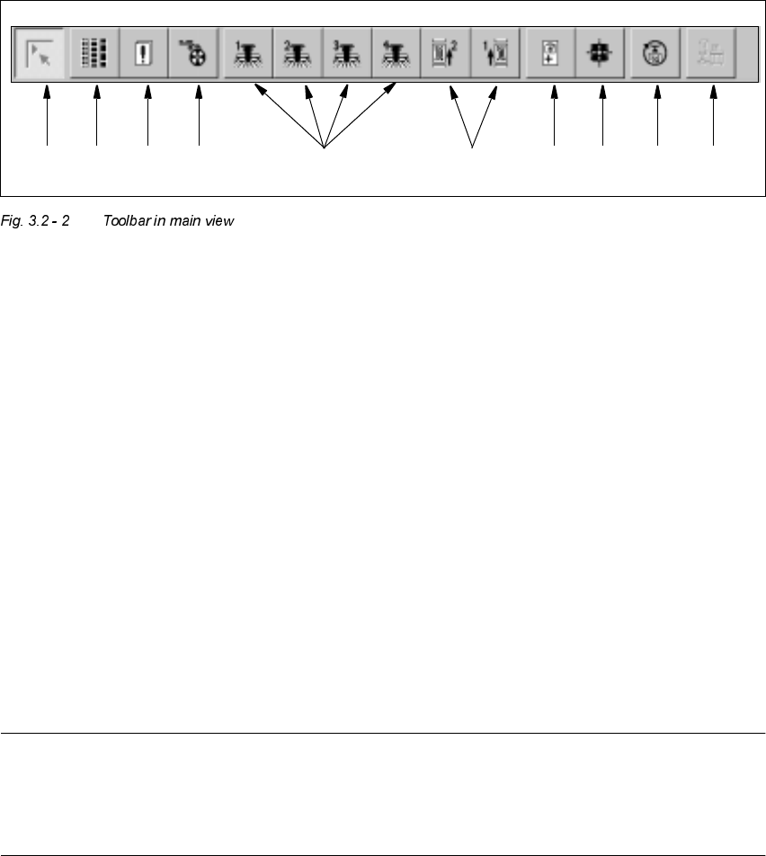
7RROEDULQ0DLQ9LHZ
.H\WR)LJXUH
(1) Main view
(2) Set-up, placement functions (for a description see Chapter 4)
(3) Error, placement functions (for a description see Chapter 4)
(4) Component feeder, placement functions(for a description see Chapter 4)
(5) Gantry 1 to 4, single functions (for a description see Chapter 5)
(6) Conveyor 1 and 2, single functions (for a description see Chapter 5)
(7) Teach fiducials, vision functions (for a description see Chapter 6)
(8) Test component, vision functions (for a description see Chapter 6)
(9) Start SITEST test program (for a description see User’s Manual
"Test Program SITEST")
(10) GEM interface (for a description see Chapter 13)
NOTES to points 6 and 10
The single functions for Conveyor 2 can only be called if a twin conveyor has been configured.
The GEM interface functions cannot be called unless this has been configured.
The "GEM Interface" option cannot be configured in the current software version.
Å Click the required button in the toolbar.
The user interface is switched to the corresponding view.
The button corresponding to the view which is currently active itself becomes inactive.
1 8 9 10765432