00191369-01.pdf - 第108页
3 Introduction and Basic Concepts User’ s M anual SIPLACE HS -50 3.2 Principles of the Graphic User I nterface Software Version SR.501.xx Edition 01/99 106 7 RROEDUL Q0DLQ9 LHZ .H\WR)LJXUH (1) M…
User’s Manual SIPLACE HS-50 3 Introduction and Basic Concepts
Software Version SR.501.xx Edition 01/99 3.2 Principles of the Graphic User Interface
105
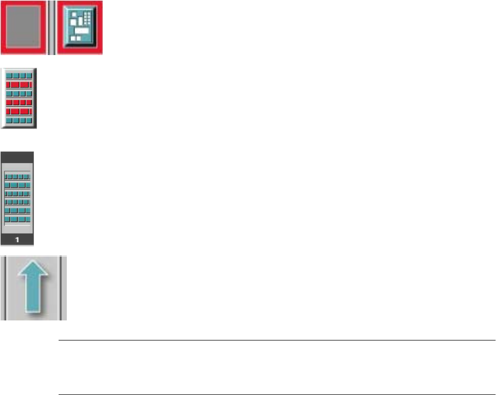
0HDQLQJRI2WKHU,FRQVDQG0DUNLQJV
If a track error, machine error or conveyor error occurs, then the corresponding graphic is
highlighted in red (see examples below).
Examples: If an error occurs in a processing area, then this is displayed with a red
border.
You can abort processing of the PCB which is located in this area by clicking the
PCB icon.
If a conveyor error occurs during transport, this is indicated by the presence of red
bars on the left and right.
If a track error occurs (e.g. missing components), then individual parts of the
graphic which correspond to the layout of the current feeder location are
displayed
against a red background. In addition, the graphic is displayed with a contour.
If you click this graphic, you can use the corresponding function to "refill" the
location (see Chapter 4).
0DFKLQHHUURU
&RPSRQHQWVPLVVLQJDWIHHGHUORFDWLRQ
)HHGHUORFDWLRQIXOO
&RQYH\RUVHWWR7UDQVSRUWWKURXJK
NOTE
This means that the "Process PCB" function is deactivated in the machine options.
The PCBs are passed through the entire transport process without being processed.
3 Introduction and Basic Concepts User’s Manual SIPLACE HS-50
3.2 Principles of the Graphic User Interface Software Version SR.501.xx Edition 01/99
106
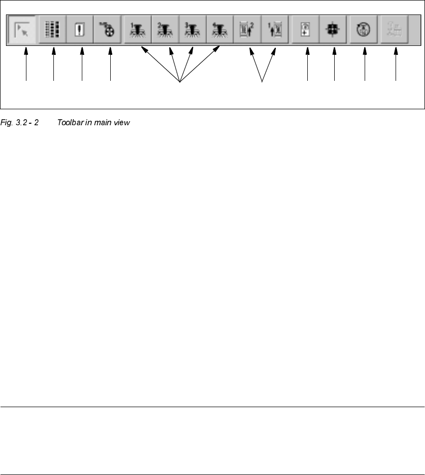
7RROEDULQ0DLQ9LHZ
.H\WR)LJXUH
(1) Main view
(2) Set-up, placement functions (for a description see Chapter 4)
(3) Error, placement functions (for a description see Chapter 4)
(4) Component feeder, placement functions(for a description see Chapter 4)
(5) Gantry 1 to 4, single functions (for a description see Chapter 5)
(6) Conveyor 1 and 2, single functions (for a description see Chapter 5)
(7) Teach fiducials, vision functions (for a description see Chapter 6)
(8) Test component, vision functions (for a description see Chapter 6)
(9) Start SITEST test program (for a description see User’s Manual
"Test Program SITEST")
(10) GEM interface (for a description see Chapter 13)
NOTES to points 6 and 10
The single functions for Conveyor 2 can only be called if a twin conveyor has been configured.
The GEM interface functions cannot be called unless this has been configured.
The "GEM Interface" option cannot be configured in the current software version.
Å Click the required button in the toolbar.
The user interface is switched to the corresponding view.
The button corresponding to the view which is currently active itself becomes inactive.
1 8 9 10765432

User’s Manual SIPLACE HS-50 3 Introduction and Basic Concepts
Software Version SR.501.xx Edition 01/99 3.3 User Interface - Views and Menus
107
8VHU,QWHUIDFH9LHZVDQG0HQXV
9L HZV
To perform a particular operation at a particular moment via the user interface, you may need
to switch this to a different view. You can do this by clicking the appropriate toolbar button (see
section 3.2.2.2) or by selecting the corresponding menu item in the "View" menu (see section
3.3.2.2).
NOTE
For a description of the functions available in the various views, refer to the chapters which
explain the procedures applicable to the operations to be performed (e.g. "Refilling Empty
Tracks", Chapter 4).