00191369-01.pdf - 第129页
User’s Manual SIPLACE HS-50 4 Placement Functions Software Vers ion SR.501.xx E dition 01/99 4.1 Setup Display 127 .H\W R)LJ (1) Display the setup for location 1 (2) Display the setup for location 2 (3) Disp…
4 Placement Functions User’s Manual SIPLACE HS-50
4.1 Setup Display Software Version SR.501.xx Edition 01/99
126
6HWXS'LVSOD\
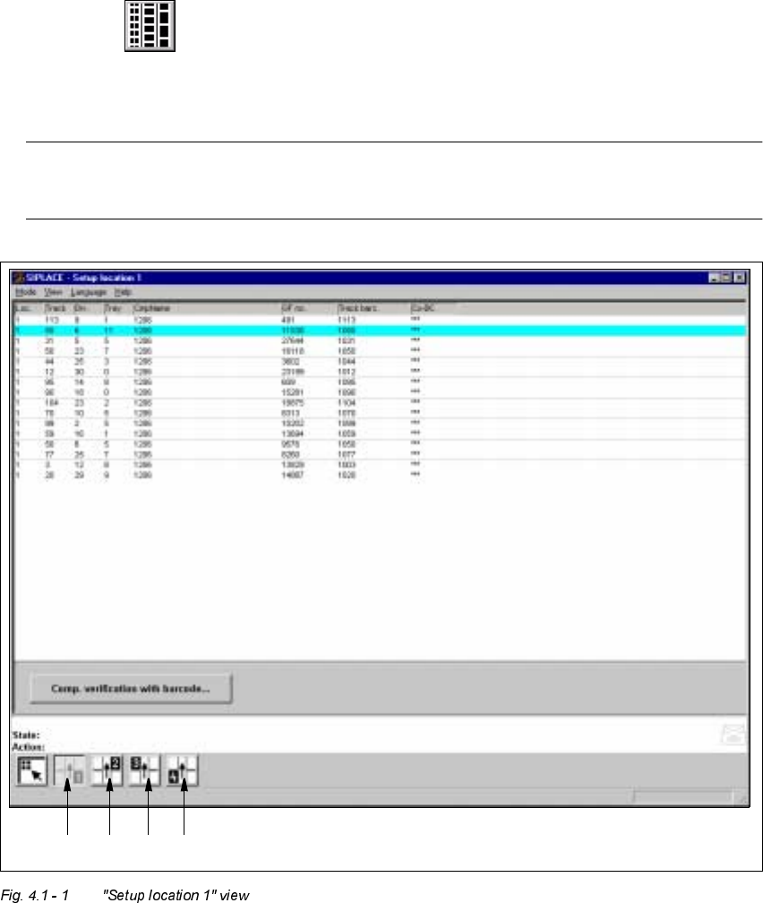
If the cluster has been specified with its corresponding setup, then the setup of each of the 4
locations can be displayed in this view.
6HWX SORFDWLRQ[9LHZ
Å Click on the icon in the toolbar in the Main view.
The user interface switches to the "Setup location x" view.
The setup data for the current location is presented in the display area in tabular form.
NOTE
The view is the same for each location.
1234

User’s Manual SIPLACE HS-50 4 Placement Functions
Software Version SR.501.xx Edition 01/99 4.1 Setup Display
127
.H\WR)LJ
(1) Display the setup for location 1
(2) Display the setup for location 2
(3) Display the setup for location 3
(4) Display the setup for location 4
0HDQLQJRIWKH(QWULHVLQWKH6HWXS7DEOH
– /RF
The number of the location whose setup is to be displayed is entered in this column. (See
Chapter 3, Fig. 3.1 - 2
for the position of the locations)
– 7UDFN
The number of the track on which the corresponding feeder is located is entered here.
– 'LY
The number of the feeder division from which the component in the corresponding feeder
is to be picked is entered in this column.
NOTE
The number for a tray division can also be entered here for other types of machines in the
SIPLACE series.
– 7UD\
This column is irrelevant when setting up the locations of a SIPLACE HS-50.
(Only valid for automatic machines with wafflepack changers).
– &PS1DPH
The name of the corresponding component is entered in this column.
– *)QR
The number of the package form for the corresponding component is entered here.
– 7UDFNEDUF
The track barcode assigned to the corresponding track is entered in this column.

4 Placement Functions User’s Manual SIPLACE HS-50
4.1 Setup Display Software Version SR.501.xx Edition 01/99
128
– &2%&
This column shows whether or not a component barcode has been specified for the corre-
sponding component in the setup using the "***" or "-" symbol.
A barcode is specified for the component.
The "Comp. verification with barcode ..." button is active when you click
on these lines in the table (see Section 4.1.2
).
- No barcode is specified for the component.
(The "Comp. verification with barcode ..." button is not active).
&RPSRQHQW9HULILFDWLRQ:LWK%DUFRGH
You prevent a track from being refilled with the wrong components with this function when re-
filling components with a specified component barcode.
The operator reads the track barcode and then the component barcode with the barcode rea-
der (see Chapter 12) . The two barcode assignments are compared with the help of the SC
software. Incorrect assignments are not accepted.
5HTXLUHPHQWV
– The barcode reader must be connected to the station computer.
– The "Track BC" option must be activated on the line computer (in the configuration editor)
for the corresponding station. (Only then will the "Component verification with barcode" op-
tion be displayed in the machine options on the station computer).
– The barcodes for the corresponding components must have been entered on the line com-
puter with the help of the component editor.
(A maximum of 6 different barcodes can be entered for a component at the present time).
– The "Component verification with barcode" option must be active in the machine options.
3URFHGXUH
Å Open the 2SWLRQVmenu in the Main view and click on the 0DFKLQHRSWLRQVmenu op-
tion. The "Machine options" window is opened (see Chapter 3).
Å Activate the checkbox for "Component verification with barcode".
Å Click on $SSO\. The window closes.
Å Switch the user interface to the "Setup location x" view.
Å Click on the icon in the toolbar for the desired location (see Fig. 4.1 - 1).