00191369-01.pdf - 第180页
5 Single Functions User’s Manual SIPLACE HS-50 5.3 Single functions, T ransport Software Version SR.501.xx Edition 01/99 178

User’s Manual SIPLACE HS-50 5 Single Functions
Software Version SR.501.xx Edition 01/99 5.3 Single functions, Transport
177
*HQHUDOFRPPHQWV
The "PCB conveyor width" screen makes available all functions necessary to adjust the width
of the conveyor.
It may be necessary to change the width of the conveyor, for example, for maintenance work
or when introducing a board with new dimensions.
The conveyor can be adjusted to suit the width of the board.
Incremental width adjustments are made by clicking the buttons "Larger" or "Smaller" (see sec-
tion 5.3.2.2
).
Width adjustments can be made in large increments (increment size = 1 mm) or in smaller steps
(increment size = 0,1 mm). This can be controlled by activating or deactivating the "High speed"
check box in the "Width adjustment" area (see section 5.3.2.2
).
)XQFWLRQV
0HDVXUHZLGWK
This function can be used to measure the current width of the conveyor. The result is shown
and saved.
Å Click the 0HDVXUHZLGWKbutton.
The measured width is displayed above the button.
,QFUHPHQWDODGMXVWPHQW
Å Activate the "High speed" check box to adjust the conveyor width in large increments.
Deactivate the check box if you want to adjust the conveyor width in smaller steps.
&RQYH\RUZLGWKDGMXVWPHQW
/DUJHU
Å Click the /DUJHUbutton to increase the width of the conveyor.
Each time you click the button the width is increased by the increment size set using the
"High speed" check box.
6PDOOHU
Å Click the 6P DOOHUbutton to reduce the width of the conveyor.
Each time you click the button the width is reduced by the increment size set using the
"High speed" check box.
r
5 Single Functions User’s Manual SIPLACE HS-50
5.3 Single functions, Transport Software Version SR.501.xx Edition 01/99
178
User Manual HS-50 6 Vision functions
Software-Version 5.01Edition 01/99 6.1 The vision systems on the placement system
179
9 LVLRQIXQFWLRQV
7KHYLVLRQV\VWHPVRQWKHSO DFHPHQWV\VWHP
The quality requirements concerning the accuracy of automatic placement systems are constantly
rising, for several reasons:
– continuing miniaturization of components,
– increasing lead connection density,
– increasing complexity of PCBs and
– increasing component density.
To help meet these requirements, high-precision mechanical components are combined with op-
tical centering and detection systems (known as vision systems) for components and PCBs.
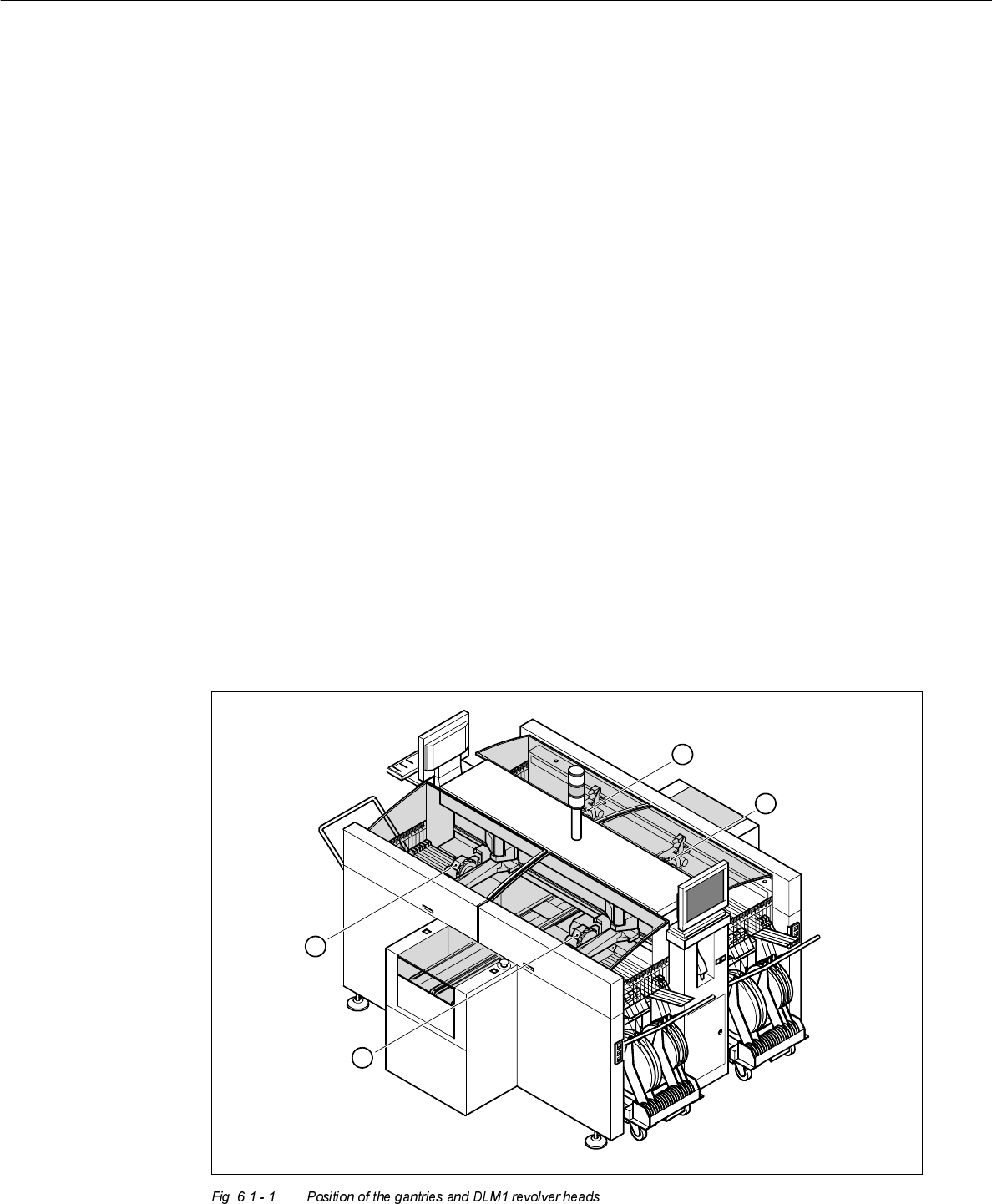
The placement system has four gantries (see Fig. 6.1 - 1). On each of these gantries there is a
DLM1 revolver head with a separate component camera system (see Fig. 6.1 - 2). A PCB camera
system is mounted on the underside of the head mount of each gantry (see Fig. 6.1 - 3).
4
1
2
3