00191369-01.pdf - 第183页
User Manual HS-50 6 Vision functions Software-Version 5.01Edition 01/99 6.1 The vision systems on the placement system 181 .H\W R)LJ (1) 12-n ozzle revolve r head /DL M1 (2) 24 x 24 component cam era (3) C…
6 Vision functions User Manual HS-50
6.1 The vision systems on the placement system Software-Version 5.01 Edition 01/99
180
(1) Gantry 1 with DLM1 revolver head and component and PCB vision system
(2) Gantry 2 with DLM1 revolver head and component and PCB vision system
(3) Gantry 3 with DLM1 revolver head and component and PCB vision system
(4) Gantry 4 with DLM1 revolver head and component and PCB vision system
9LVLRQDQDO\VLVXQLWV
The two vision analysis units plug into the control unit (see items 1 and 2 in Fig. 6.1 - 4). The com-
ponent and PCB cameras, combined with the vision analysis units form the vision system.
The electrical image signals from the component and PCB camera systems are sent to the vision
analysis units (see items 1 and 2 in Fig. 6.1 - 4), where the measured values are compared with
the artificial values from the component description or PCB fiducials. The result is used to calcu-
late the correction factors for the individual placement positions.
The components are also identified by their package forms. The component is not placed if the
artificial model and the package form measurement do not correspond.
The PCB vision system can also be used to detect the position of the feeder modules. Fiducials
on the feeder modules are used to calculate the position deviation of individual feeder modules.
The pick-up reliability can be greatly increased in this way, even for tiny components.
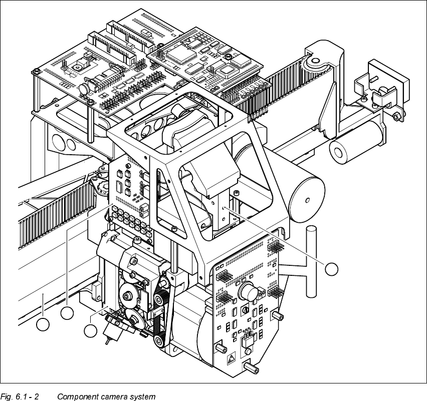
&RPSRQHQWFDP HUDV\VWHPRQWKHUHYROYHUKHDG
The component camera system (see item 2 in Fig. 6.1 - 2) essentially consists of the following
modules:
– Lens system
– CCD chip for creating an electronic image of the component
– CCD camera amplifier
– Three illumination planes - flat, medium and steep - for optimum lighting of a wide range of
component shapes
– "Illumination control" board for setting the intensity of the individual illumination planes
User Manual HS-50 6 Vision functions
Software-Version 5.01Edition 01/99 6.1 The vision systems on the placement system
181
.H\WR)LJ
(1) 12-nozzle revolver head /DLM1
(2) 24 x 24 component camera
(3) Component illumination control board
(4) Gantry
The component camera system is fastened to the top of the revolver head with four hexagon
socket-head screws and is fixed in position with two parallel pins.
The component camera system can be used to optically center and place components ranging
from 0402 up to and including SO32 in size. The components, therefore, can vary between
1.0 mm x 0.5 mm and 18.7 mm x 18.7 mm in size and from 0.3 mm to 6 mm thick. The minimum
lead pitch can be as little as 0.5 mm.
2
1
3
4
6 Vision functions User Manual HS-50
6.1 The vision systems on the placement system Software-Version 5.01 Edition 01/99
182
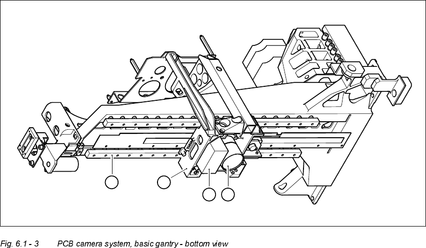
3&%FDPHUDV\VWHPV
.H\WR)LJ
(1) PCB camera - lens and illumination
(2) Camera amplifier
(3) Head mount
(4) Gantry
The PCB camera system (see items 1 and 2 in Fig. 6.1 - 3) essentially consists of the following
components:
– Lens system
– CCD chip
– CCD camera amplifier
– An illumination plane for illuminating PCB fiducials and ink spots
The PCB camera system is fixed to the revolver head mount on the underside of the gantry. As
standard, it can center PCBs from 50 mm x 50 mm up to 368 mm x 460 mm (2" x 2" to 14.5" x 18")
in size, with the thickness ranging from 0.5 mm to 4.5 mm.
1
2
4
3